Download
1 / 15
260 likes | 725 Views
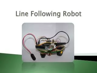
Line following robot. BADI Year 3 John Errington MSc. Specifications. Self-powered – implies recharging or refuelling Operating schedule How long must it operate between recharges What time is available for recharging Outside dimensions and turning circle

E N D
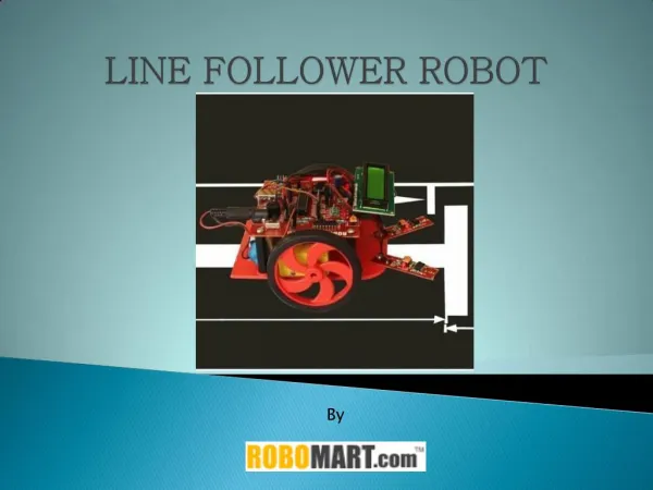
Line following robot BADI Year 3 John Errington MSc
Specifications • Self-powered – • implies recharging or refuelling • Operating schedule • How long must it operate between recharges • What time is available for recharging • Outside dimensions and turning circle • Related to spaces it must travel through • Nature of environment – clean, dirty, presence of contaminants, oil, swarf, other moving objects, need for rerouting of track etc. • Carrying capacity • Max speed and braking, • Max gradient and irregularity of floor • The latter points determine the amount of motive power needed, and this must be related to operating schedule • Safety considerations
Engineering Design issues 1: line detection • What kind of track options: • Metal, optical: reflective, white or black? • How will the track be detected? • Will the detection scheme be on/off or proportional? (prop’l is less reliable) • How will stops, accel & decel zones, changes in direction be signalled?
Engineering Design issues 2: motive power • Electric, hydraulic, pneumatic • Source(s) of energy: • Fuel: petrol, diesel, paraffin, coal, LP gas, hydrogen etc. • Rechargeable batteries – what kind? • Motors • What type(s)? How many? How will they be controlled? • Final drive gear, belt, chain, direct • Wheels, tracks, legs, other?
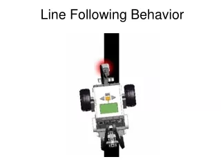
Line detection • How many sensors are needed? • One sensor • can detect presence of line, but not direction of line loss • Two sensors • Can detect direction of line loss in simple situations, but relies upon dithering to check for line • Three sensors • Can detect presence of line and direction of line loss • Allows for other simple signals to indicate stops and accel/decel zones.
3-sensor line detection: further A more detailed appraisal shows that the information available for decision-making includes • The current state of the line sensors • The previous state of the line sensors • Taking three sensors this implies 2^(3*2) • giving 64 possible states.
State transition diagram • A simpler way to represent this information involves • assigning input values to all possible input events, and • state values to all possible end results • A map is then produced showing the change in output state that will result following each input state
State transition diagram • A std allows the conditions that cause changes between states, and the responses required to be shown on a visual plan.
Partially completed state transition diagram I1 1 5 I0 2 I0 6 I1 3 4 7 8
Analysis of S.T.D. • An engineer can use the STD to design a logic circuit that will produce the required responses to the various input conditions as shown on the map.
Partial state table and STD 1 I1 5 2 I0 I0 6 I1 3 4 7 8
Motor calculation • Suppose the maximum speed required is 5 kph • Suppose the maximum gradient in the factory is 1/100 Then in travelling up this gradient for 1 hour the robot would rise by 5km / 100 = 50m • Suppose the robot has a mass of 1000kg when fully loaded – its weight is = 1000kg *9.81 N
Size of motor Force = 1000 * 9.81 Newtons Work done in raising 9810N through 50m: W = 9810 * 50 = 490500 J(Work = force * distance) Power is total work done (J) / time taken (sec) Power (Watts) = 490500 / 60 * 60 = 135 Watts Or since 1hp = 0.75kW we need a 0.25 hp motor