Download
1 / 14
150 likes | 484 Views
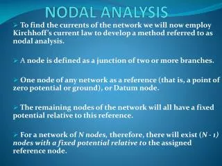
Chapter 3 – Nodal Analysis. Read pages 65 - 80. Nodal Analysis: Nodal analysis is a systematic application of KCL that generates a system of equations which can be solved to find voltage at each node in a circuit. (We sum currents at each node to find the node voltages .). Homework:

E N D
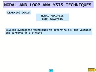
Chapter 3 – Nodal Analysis Read pages 65 - 80 Nodal Analysis: Nodal analysis is a systematic application of KCL that generates a system of equations which can be solved to find voltage at each node in a circuit. (We sum currents at each node to find the node voltages.) • Homework: • online HW, Nodal #1 and Nodal #2 • 3FE-1 and 3FE-3 • Due 9/24/01 ENGR201 Nodal Analysis
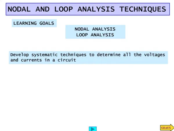
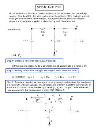
Nodal Analysis Steps: • Label all nodes in the circuit, • Select one node as the reference node (also called common). The voltage at every other other node in the circuit is measured with respect to the reference node. • Write a KCL equation (i = 0) at each node. • Solve the resulting set of equations for the node voltages. • Branches connected to a node will have one of three types of elements: • current sources (independent or dependent) • resistors • voltage sources (independent or dependent) ENGR201 Nodal Analysis
Nodal Analysis – Branches With Curent Sources Since we are applying KCL, current sources (either independent or dependent) connected to a node provide terms for our KCL equation that we can write down by inspection. IS = IR1 + IR2 + IR3 The next step is to write each resistive current in terms of the node voltages. If a current source is dependent, we must also write the dependent current in terms of the node voltages. ENGR201 Nodal Analysis
Nodal Analysis – Resistive Branches + VAB - + VA - IAB + VB - By KVL, the voltage drop from node-A to node-B is the difference between the voltage at node-A (VA0 = VA) and the voltage at node-B (VB0 = VB) . The current leaving node-A going toward node-B, IAB, is: The current leaving node-B going toward node-A is: R A B Consider a single resistor connected between two arbitrary nodes: 0 V ENGR201 Nodal Analysis
Example 1 B I2 A E R1 R3 X R2 I1 D C 0 currents leaving node-X resistive branches currents entering node-X current Sources If we apply the previous techniques to the resistors connected to node-X in the following circuit and apply KCL at node-X, we get the following equation. Note that the equation should have five terms since there are five branches connected to node-X and each branch will have a corresponding current ENGR201 Nodal Analysis
Example 2 Ix V1 V2 12 k Ix 4 mA 6 k 6 k 2 mA Use nodal analysis to find Ix. 12 k 2 mA 4 mA 6 k 6 k Step 1, Label nodes: ENGR201 Nodal Analysis
Example 2 - continued V1 V2 12 k Ix 4 mA 6 k 6 k 2 mA Use nodal analysis to find Ix. Step 2: Write KCL equations at each node (except reference node): ENGR201 Nodal Analysis
Example 2 - continued V1 V2 12 k Ix 4 mA 6 k 6 k 2 mA Use nodal analysis to find Ix. In matrix form: Solving these equations (shown on the following slide) yields: V1 = -15 V and V2 = 3 V. ENGR201 Nodal Analysis
Example 2 - continued V1 = -15 V V2 = 3 V 12 k Ix 4 mA 6 k 6 k 2 mA Use nodal analysis to find Ix. In terms of the node voltages: Ix = (V1 - V2)/12k = (-15 – 3)/12 k = -18v/ 12k Ix = -1.5mA ENGR201 Nodal Analysis
TI-86 Solution 3 1 2 4 ENGR201 Nodal Analysis
TI-86 Solution 5 7 6 ENGR201 Nodal Analysis
Dependent Sources • Circuits containing dependent sources generally introduce another unknown - the parameter (voltage or current) that controls the dependent source. • This requires that the additional unknown be eliminated by writing an equation that expresses the controlling parameter in terms of the node voltages. • The resulting equations, with the additional unknown eliminated, are solved in a conventional manner. • The following example illustrates. ENGR201 Nodal Analysis
Dependent Source Example R2 Io R3 R1 Io IS V1 V2 The nodal equations are: Node #1: Node #2: • There are three unknowns in the equations, V1, V2 and Io. • Another equation is needed that relates Io to V1 and/or V2. The additional equation can be formed by noting the Io is the current through R3, and by Ohm’s law Io = V2/R3. This relation can be used to form a system of three- equations or to eliminate Io from the first equation, leaving a two-by-two system to solve. ENGR201 Nodal Analysis
Example 3 V1 V2 2Io Io The “extra” unknown, Io, can be expressed as: The equations become: Use nodal analysis to find node voltages V1 and V2. The node equations are: ENGR201 Nodal Analysis