Download
1 / 26
260 likes | 411 Views
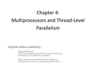
Lecture 17: Instruction Level Parallelism (ILP) & Input/Output (I/O). Michael B. Greenwald Computer Architecture CIS 501 Fall 1999. Administration. HW #4 due today. HW #5 being handed out. (Notice it is due in 1 week!) Schedule: office hours are 1/2 hour early on Thursday

E N D
Lecture 17:Instruction Level Parallelism (ILP)&Input/Output (I/O) Michael B. Greenwald Computer Architecture CIS 501 Fall 1999
Administration • HW #4 due today. HW #5 being handed out. (Notice it is due in 1 week!) • Schedule: office hours are 1/2 hour early on Thursday • Schedule: I will be gone on November 18th, Sotiris will cover the lecture.
Syllabus • Advanced Pipelining • Loop level parallelism • Dynamic scheduling: scoreboarding • Dynamic branch prediction, speculation, predication • Multiple issue: superscalar vs. VLIW • Storage & I/O: just buses • Schedule: We will cover: • Intro to Chapter 4 • Buses (from Chapter 6) • rest of chapter 4
Introduction to Exploiting Instruction Level Parallelism (ILP) Software and Hardware techniques
Instruction Level Parallelism (ILP) • Review: • Goal of ILP is to exploit parallelism within and among instructions. • Basic technique is to overlap independent operation (within instruction => stages of pipeline, between instructions => reordering) • Optimal speedup (so far) = depth of pipeline, but can be reduced by hazards • Maximize parallelism by reducing hazards (structural, control, and data dependencies) • Parallelism within basic block is limited, given that 15-20% of instructions are branches, so we need to exploit parallelism between basic blocks.
Loop Level ParallelismFP Loop: Where are the Hazards? Loop: LD F0,0(R1) ;F0=vector element ADDD F4,F0,F2 ;add scalar in F2 SD 0(R1),F4 ;store result SUBI R1,R1,8 ;decrement pointer 8B (DW) BNEZ R1,Loop ;branch R1!=zero NOP ;delayed branch slot • Where are the stalls? Instruction Instruction Latency inproducing result using result clock cycles FP ALU op Another FP ALU op 3 FP ALU op Store double 2 Load double FP ALU op 1 Load double Store double 0 Integer op Integer op 0
FP Loop Showing Stalls 1 Loop: LD F0,0(R1) ;F0=vector element 2 stall 3 ADDD F4,F0,F2 ;add scalar in F2 4 stall 5 stall 6 SD 0(R1),F4 ;store result 7 SUBI R1,R1,8 ;decrement pointer 8B (DW) 8stall 9 BNEZ R1,Loop ;branch R1!=zero 10 stall ;delayed branch slot • Rewrite code to minimize stalls? 10 Cycles per loop Instruction Instruction Latency inproducing result using result clock cycles FP ALU op Another FP ALU op 3 FP ALU op Store double 2 Load double FP ALU op 1
Revised FP Loop Minimizing Stalls 1 Loop: LD F0,0(R1) 2 SUBI R1,R1,8 3 ADDD F4,F0,F2 4 stall 5 BNEZ R1,Loop ;delayed branch 6 SD 8(R1),F4;altered when move past SUBI Unroll loop 4 times code to make faster? 6 Cycles per loop Instruction Instruction Latency inproducing result using result clock cycles FP ALU op Another FP ALU op 3 FP ALU op Store double 2 Load double FP ALU op 1
Unrolled (4x) LoopOriginal: 10 cycles/iteration 1 stall 1 Loop: LD F0,0(R1) 2 ADDD F4,F0,F2 3 SD 0(R1),F4 ;drop SUBI & BNEZ 4 LD F6,-8(R1) 5 ADDD F8,F6,F2 6 SD -8(R1),F8 ;drop SUBI & BNEZ 7 LD F10,-16(R1) 8 ADDD F12,F10,F2 9 SD -16(R1),F12 ;drop SUBI & BNEZ 10 LD F14,-24(R1) 11 ADDD F16,F14,F2 12 SD -24(R1),F16 13 SUBI R1,R1,#32;alter to 4*8 14 BNEZ R1,LOOP 15 NOP 15 + 4 x (1+2) = 27 clock cycles, or 6.8 per iteration Assumes R1 is multiple of 4; avoids loop overhead. Rewrite loop to minimize stalls? 6.8 Cycles per loop 2 stalls
Unrolled Loop That Minimizes Stalls 1 Loop: LD F0,0(R1) 2 LD F6,-8(R1) 3 LD F10,-16(R1) 4 LD F14,-24(R1) 5 ADDD F4,F0,F2 6 ADDD F8,F6,F2 7 ADDD F12,F10,F2 8 ADDD F16,F14,F2 9 SD 0(R1),F4 10 SD -8(R1),F8 11 SD -16(R1),F12 12 SUBI R1,R1,#32 13 BNEZ R1,LOOP 14 SD 8(R1),F16 ; 8-32 = -24 14 clock cycles, or 3.5 per iteration 3.5 Cycles per loop • What assumptions made when moved code? • OK to move store past SUBI even though changes register • OK to move loads before stores: get right data? • When is it safe for compiler to make such changes?
Compiler Perspectives on Code Movement • Definitions: compiler concerned about dependencies in program, whether or not a HW hazard depends on a given pipeline • (True) Data dependencies (RAW if a hazard for HW) • Instruction i produces a result used by instruction j, or • Instruction j is data dependent on instruction k, and instruction k is data dependent on instruction i. • Easy to determine for registers (fixed names) • Hard for memory: • Does 100(R4) = 20(R6)? • From different loop iterations, does 20(R6) = 20(R6)?
Compiler Perspectives on Code Movement • Another kind of dependence called name dependence: two instructions use same name but don’t exchange data • Antidependence (WAR if a hazard for HW) • Instruction j writes a register or memory location that instruction i reads from and instruction i is executed first • Output dependence (WAW if a hazard for HW) • Instruction i and instruction j write the same register or memory location; ordering between instructions must be preserved.
Compiler Perspectives on Code Movement • Again Hard for Memory Accesses • Does 100(R4) = 20(R6)? • From different loop iterations, does 20(R6) = 20(R6)? • Our example required compiler to know that if R1 doesn’t change then:0(R1) ^= -8(R1) ^= -16(R1) ^= -24(R1) There were no dependencies between some loads and stores so they could be moved by each other
Compiler Perspectives on Code Movement • Final kind of dependence called control dependence • Example if p1 {S1;}; if p2 {S2;} S1 is control dependent on p1 and S2 is control dependent on p2 but not on p1.
Compiler Perspectives on Code Movement • Two (obvious) constraints on control dependences: • An instruction that is control dependent on a branch cannot be moved before the branch so that its execution is no longer controlled by the branch. • An instruction that is not control dependent on a branch cannot be moved to after the branch so that its execution is controlled by the branch. • Control dependencies relaxed to get parallelism; get same effect if preserve order of exceptions and data flow
Loop Level ParallelismWhen Safe to Unroll Loop? • Example: Where are data dependencies? (A,B,C distinct & nonoverlapping: in practice, hard )for (i=1; i<=100; i=i+1) { A[i+1] = A[i] + C[i]; /* S1 */ B[i+1] = B[i] + A[i+1];} /* S2 */ 1. S2 uses the value, A[i+1], computed by S1 in the same iteration. 2. S1 uses a value computed by S1 in an earlier iteration, since iteration i computes A[i+1] which is read in iteration i+1. The same is true of S2 for B[i] and B[i+1]. This is a “loop-carried dependence”: between iterations • Circular loop carried dependence implies that iterations are dependent, and can’t be executed in parallel • Not the case for our example; each iteration was distinct
Loop Level ParallelismWhen Safe to Unroll Loop? • Example: Where are data dependencies? (A,B,C & D distinct & nonoverlapping)for (i=1; i<=100; i=i+1) { A[i] = A[i] + B[i]; /* S1 */ B[i+1] = C[i] + D[i];} /* S2 */ 1. S1 has loop-carried dependence (A[i] = f(B[i]), B[i] produced last iteration in S2.2. S2 has no dependencies. • Non-Circular loop carried dependence so can be translated: A[1] = A[1]+B[1]; for (i=1; i<=99; i=i+1) { B[i+1] = C[i] + D[i]; A[i+1] = A[i+1] + B[i+1]; } B[101] = C[100] + D[100];
ExploitingInstruction Level Parallelism • Data dependencies limit how much ILP can be exploited • Compiler: Eliminate or minimize dependencies • Hardware: Prevent dependencies from becoming stalls. Challenge: approach the limit defined by data dependencies
Summary • Instruction Level Parallelism in SW or HW • Loop level parallelism is easiest to see • SW parallelism dependencies defined for program, hazards if HW cannot resolve • SW dependencies/compiler sophistication determine if compiler can unroll loops
Scheduling • Scheduling does not remove dependencies, it just reduces hazards/stalls. • So far we’ve discussed static scheduling: • separate dependent instructions to minimize hazards/stalls • Problems: • Compiler needs to know a lot about u-architecture • Dependencies must be known at compile time (e.g. memory) • Complex compiler • Alternative: dynamic scheduling = HW rearranges instructions during execution to reduce stalls.
I/O Systems interrupts Processor Cache Memory - I/O Bus Main Memory I/O Controller I/O Controller I/O Controller Graphics Disk Disk Network Time(workload) = Time(CPU) + Time(I/O) - Time(Overlap)
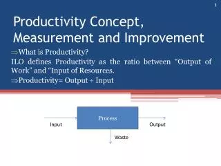
Motivation: Who Cares About I/O? • CPU Performance: 50% to 100% per year • Multiprocessor supercomputers 150% per year • I/O system performance limited by mechanical delays < 5% per year (IO per sec or MB per sec) • Amdahl's Law: system speed-up limited by the slowest part! 10% IO & 10x CPU => 5x Performance (lose 50%) 10% IO & 100x CPU => 10x Performance (lose 90%) • I/O bottleneck: Diminishing fraction of time in CPU Diminishing value of faster CPUs
Bus-Based Interconnect • Bus: a shared communication path between subsystems • Low cost: a single set of wires is shared multiple ways • Versatility: Easy to add new devices & peripherals may even be ported between computers using common bus (standardization) • Disadvantage • A communication bottleneck, possibly limiting the maximum I/O throughput, (eventually limiting system performance) • Bus speed is limited by physical factors • the bus length • the number of devices (and, hence, bus loading). • these physical limits prevent arbitrary bus speedup.
Bus-Based Interconnect • Two generic types of busses: • I/O busses: lengthy, many types of devices connected, wide range in the data bandwidth, and follow a bus standard.Sometimes called a channel. • CPU–memory buses: high speed, matched to the memory system to maximize memory–CPU bandwidth, single device (actually, also a small number of devices, but known in advance!). Sometimes called a backplane. • To lower costs, low cost (older) systems combine the memory and I/O buses in one shared bus • Often, system starts with one shared bus, but memory and CPU increase in speed faster than devices do, so old memory bus becomes new I/O bus. • Bus transaction • Sending address & receiving or sending data