Download
1 / 151
1.54k likes | 1.71k Views
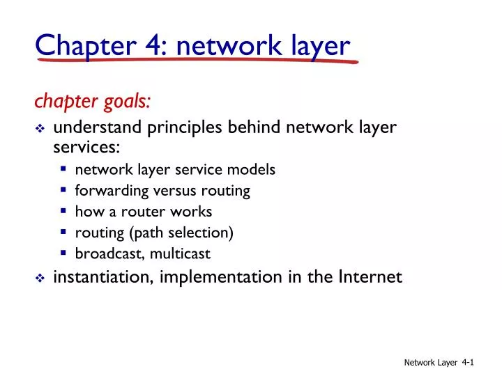
Chapter 4: network layer. chapter goals: understand principles behind network layer services: network layer service models forwarding versus routing how a router works routing (path selection) broadcast, multicast instantiation, implementation in the Internet. 4.1 introduction

E N D
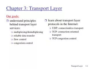
Chapter 4: network layer chapter goals: • understand principles behind network layer services: • network layer service models • forwarding versus routing • how a router works • routing (path selection) • broadcast, multicast • instantiation, implementation in the Internet Network Layer
4.1 introduction 4.2 virtual circuit and datagram networks 4.3 what’s inside a router 4.4 IP: Internet Protocol datagram format IPv4 addressing ICMP IPv6 4.5 routing algorithms link state distance vector hierarchical routing 4.6 routing in the Internet RIP OSPF BGP 4.7 broadcast and multicast routing Chapter 4: outline Network Layer
transport segment from sending to receiving host on sending side encapsulates segments into datagrams on receiving side, delivers segments to transport layer network layer protocols in everyhost, router router examines header fields in all IP datagrams passing through it network data link physical network data link physical network data link physical network data link physical network data link physical network data link physical network data link physical network data link physical network data link physical network data link physical network data link physical application transport network data link physical application transport network data link physical Network layer Network Layer
Two key network-layer functions analogy: • routing: process of planning trip from source to dest • forwarding: process of getting through single interchange • forwarding: move packets from router’s input to appropriate router output • routing: determine route taken by packets from source to dest. • routing algorithms Network Layer
routing algorithm local forwarding table header value output link routing algorithm determines end-end-path through network forwarding table determines local forwarding at this router 0100 0101 0111 1001 3 2 2 1 value in arriving packet’s header 1 0111 2 3 Interplay between routing and forwarding Network Layer
Connection setup • 3rd important function in some network architectures: • ATM, frame relay, X.25 • before datagrams flow, two end hosts and intervening routers establish virtual connection • routers get involved • network vs transport layer connection service: • network: between two hosts (may also involve intervening routers in case of VCs) • transport: between two processes Network Layer
example services for individual datagrams: guaranteed delivery guaranteed delivery with less than 40 msec delay example services for a flow of datagrams: in-order datagram delivery guaranteed minimum bandwidth to flow restrictions on changes in inter-packet spacing Network service model Q: What service model for “channel” transporting datagrams from sender to receiver? Network Layer
Network layer service models: Guarantees ? Network Architecture Internet ATM ATM ATM ATM Service Model best effort CBR VBR ABR UBR Congestion feedback no (inferred via loss) no congestion no congestion yes no Bandwidth none constant rate guaranteed rate guaranteed minimum none Loss no yes yes no no Order no yes yes yes yes Timing no yes yes no no Network Layer
4.1 introduction 4.2 virtual circuit and datagram networks 4.3 what’s inside a router 4.4 IP: Internet Protocol datagram format IPv4 addressing ICMP IPv6 4.5 routing algorithms link state distance vector hierarchical routing 4.6 routing in the Internet RIP OSPF BGP 4.7 broadcast and multicast routing Chapter 4: outline Network Layer
Connection, connection-less service • datagram network provides network-layer connectionless service • virtual-circuit network provides network-layer connection service • analogous to TCP/UDP connecton-oriented / connectionless transport-layer services, but: • service:host-to-host • no choice:network provides one or the other • implementation:in network core Network Layer
call setup, teardown for each call before data can flow each packet carries VC identifier (not destination host address) every router on source-dest path maintains “state” for each passing connection link, router resources (bandwidth, buffers) may be allocated to VC (dedicated resources = predictable service) “source-to-dest path behaves much like telephone circuit” performance-wise network actions along source-to-dest path Virtual circuits Network Layer
VC implementation a VC consists of: • path from source to destination • VC numbers, one number for each link along path • entries in forwarding tables in routers along path • packet belonging to VC carries VC number (rather than dest address) • VC number can be changed on each link. • new VC number comes from forwarding table Network Layer
VC forwarding table 22 32 12 3 1 2 VC number interface number forwarding table in northwest router: Incoming interface Incoming VC # Outgoing interface Outgoing VC # 1 12 3 22 2 63 1 18 3 7 2 17 1 97 3 87 … … … … VC routers maintain connection state information! Network Layer
used to setup, maintain teardown VC used in ATM, frame-relay, X.25 not used in today’s Internet application transport network data link physical application transport network data link physical Virtual circuits: signaling protocols 6. receive data 5. data flow begins 4. call connected 3. accept call 1. initiate call 2. incoming call Network Layer
no call setup at network layer routers: no state about end-to-end connections no network-level concept of “connection” packets forwarded using destination host address application transport network data link physical application transport network data link physical Datagram networks 1. send datagrams 2. receive datagrams Network Layer
4 billion IP addresses, so rather than list individual destination address list range of addresses (aggregate table entries) 1 3 2 Datagram forwarding table routing algorithm local forwarding table dest address output link address-range 1 address-range 2 address-range 3 address-range 4 3 2 2 1 IP destination address in arriving packet’s header Network Layer
Datagram forwarding table Destination Address Range 11001000 00010111 00010000 00000000 through 11001000 00010111 00010111 11111111 11001000 00010111 00011000 00000000 through 11001000 00010111 00011000 11111111 11001000 00010111 00011001 00000000 through 11001000 00010111 00011111 11111111 otherwise Link Interface 0 1 2 3 Q: but what happens if ranges don’t divide up so nicely? Network Layer
Longest prefix matching longest prefix matching when looking for forwarding table entry for given destination address, use longest address prefix that matches destination address. Link interface 0 1 2 3 Destination Address Range 11001000 00010111 00010*** ********* 11001000 00010111 00011000 ********* 11001000 00010111 00011*** ********* otherwise examples: which interface? DA: 11001000 00010111 00010110 10100001 which interface? DA: 11001000 00010111 00011000 10101010 Network Layer
Internet (datagram) data exchange among computers “elastic” service, no strict timing req. many link types different characteristics uniform service difficult “smart” end systems (computers) can adapt, perform control, error recovery simple inside network, complexity at “edge” ATM (VC) evolved from telephony human conversation: strict timing, reliability requirements need for guaranteed service “dumb” end systems telephones complexity inside network Datagram or VC network: why? Network Layer
4.1 introduction 4.2 virtual circuit and datagram networks 4.3 what’s inside a router 4.4 IP: Internet Protocol datagram format IPv4 addressing ICMP IPv6 4.5 routing algorithms link state distance vector hierarchical routing 4.6 routing in the Internet RIP OSPF BGP 4.7 broadcast and multicast routing Chapter 4: outline Network Layer
high-seed switching fabric Router architecture overview two key router functions: • run routing algorithms/protocol (RIP, OSPF, BGP) • forwarding datagrams from incoming to outgoing link forwarding tables computed, pushed to input ports routing processor routing, management control plane (software) forwarding data plane (hardware) router input ports router output ports Network Layer
Input port functions lookup, forwarding queueing decentralized switching: • given datagram dest., lookup output port using forwarding table in input port memory (“match plus action”) • goal: complete input port processing at ‘line speed’ • queuing: if datagrams arrive faster than forwarding rate into switch fabric link layer protocol (receive) switch fabric line termination physical layer: bit-level reception data link layer: e.g., Ethernet see chapter 5 Network Layer
Switching fabrics • transfer packet from input buffer to appropriate output buffer • switching rate: rate at which packets can be transfer from inputs to outputs • often measured as multiple of input/output line rate • N inputs: switching rate N times line rate desirable • three types of switching fabrics memory bus memory crossbar Network Layer
output port (e.g., Ethernet) input port (e.g., Ethernet) memory system bus Switching via memory first generation routers: • traditional computers with switching under direct control of CPU • packet copied to system’s memory • speed limited by memory bandwidth (2 bus crossings per datagram) Network Layer
Switching via a bus • datagram from input port memory to output port memory via a shared bus • bus contention: switching speed limited by bus bandwidth • 32 Gbps bus, Cisco 5600: sufficient speed for access and enterprise routers bus Network Layer
crossbar Switching via interconnection network • overcome bus bandwidth limitations • banyan networks, crossbar, other interconnection nets initially developed to connect processors in multiprocessor • advanced design: fragmenting datagram into fixed length cells, switch cells through the fabric. • Cisco 12000: switches 60 Gbps through the interconnection network Network Layer
datagram buffer queueing Output ports • buffering required when datagrams arrive from fabric faster than the transmission rate • scheduling discipline chooses among queued datagrams for transmission switch fabric line termination link layer protocol (send) Network Layer
switch fabric switch fabric one packet time later at t, packets more from input to output Output port queueing • buffering when arrival rate via switch exceeds output line speed • queueing (delay) and loss due to output port buffer overflow! Network Layer
. RTT C N How much buffering? • RFC 3439 rule of thumb: average buffering equal to “typical” RTT (say 250 msec) times link capacity C • e.g., C = 10 Gpbs link: 2.5 Gbit buffer • recent recommendation: with N flows, buffering equal to Network Layer
switch fabric one packet time later: green packet experiences HOL blocking Input port queuing • fabric slower than input ports combined -> queueing may occur at input queues • queueing delay and loss due to input buffer overflow! • Head-of-the-Line (HOL) blocking: queued datagram at front of queue prevents others in queue from moving forward switch fabric output port contention: only one red datagram can be transferred.lower red packet is blocked Network Layer
4.1 introduction 4.2 virtual circuit and datagram networks 4.3 what’s inside a router 4.4 IP: Internet Protocol datagram format IPv4 addressing ICMP IPv6 4.5 routing algorithms link state distance vector hierarchical routing 4.6 routing in the Internet RIP OSPF BGP 4.7 broadcast and multicast routing Chapter 4: outline Network Layer
host, router network layer functions: • IP protocol • addressing conventions • datagram format • packet handling conventions forwarding table The Internet network layer transport layer: TCP, UDP • routing protocols • path selection • RIP, OSPF, BGP network layer • ICMP protocol • error reporting • router “signaling” link layer physical layer Network Layer
IP protocol version number 32 bits total datagram length (bytes) header length (bytes) type of service head. len ver length for fragmentation/ reassembly fragment offset “type” of data flgs 16-bit identifier max number remaining hops (decremented at each router) upper layer time to live header checksum 32 bit source IP address 32 bit destination IP address upper layer protocol to deliver payload to e.g. timestamp, record route taken, specify list of routers to visit. options (if any) data (variable length, typically a TCP or UDP segment) IP datagram format how much overhead? • 20 bytes of TCP • 20 bytes of IP • = 40 bytes + app layer overhead Network Layer
network links have MTU (max.transfer size) - largest possible link-level frame different link types, different MTUs large IP datagram divided (“fragmented”) within net one datagram becomes several datagrams “reassembled” only at final destination IP header bits used to identify, order related fragments … … reassembly IP fragmentation, reassembly fragmentation: in: one large datagram out: 3 smaller datagrams Network Layer
length =1500 length =1500 length =4000 length =1040 ID =x ID =x ID =x ID =x fragflag =0 fragflag =1 fragflag =1 fragflag =0 offset =0 offset =0 offset =370 offset =185 one large datagram becomes several smaller datagrams IP fragmentation, reassembly example: • 4000 byte datagram • MTU = 1500 bytes 1480 bytes in data field offset = 1480/8 Network Layer
4. 1 Introduction 4.2 Virtual circuit and datagram networks 4.3 What’s inside a router 4.4 IP: Internet Protocol Datagram format IPv4 addressing ICMP IPv6 4.5 Routing algorithms Link state Distance Vector Hierarchical routing 4.6 Routing in the Internet RIP OSPF BGP 4.7 Broadcast and multicast routing Chapter 4: Network Layer Network Layer
IPv6 • Initial motivation:32-bit address space soon to be completely allocated. • Additional motivation: • header format helps speed processing/forwarding • header changes to facilitate QoS IPv6 datagram format: • fixed-length 40 byte header • no fragmentation allowed Network Layer
IPv6 Header (Cont) Priority: identify priority among datagrams in flow Flow Label: identify datagrams in same “flow.” (concept of“flow” not well defined). Next header: identify upper layer protocol for data Data: extension headers + upper layer payload pri ver flow label hop limit payload len next hdr source address (128 bits) destination address (128 bits) data 32 bits Network Layer
Extension Header Network Layer
Other Changes from IPv4 • Checksum:removed entirely to reduce processing time at each hop • Options: allowed, but outside of header (in the “extension headers” data portion), pointed to by “Next Header” field. Upper layer protocol info is put into “Next Header” field in the last extension header • ICMPv6: new version of ICMP • additional message types, e.g. “Packet Too Big” • multicast group management functions Network Layer
Transition From IPv4 To IPv6 • Not all routers can be upgraded simultaneous • no “flag days” • How will the network operate with mixed IPv4 and IPv6 routers? • Tunneling: IPv6 carried as payload in IPv4 datagram among IPv4 routers Network Layer
IPv4 tunnel connecting IPv6 routers logical view: A A E E B B F F IPv6 IPv6 IPv6 IPv6 IPv6 IPv6 IPv6 IPv6 Tunneling C D physical view: IPv4 IPv4 Network Layer
Flow: X Src: A Dest: F data Flow: X Src: A Dest: F data IPv4 tunnel connecting IPv6 routers logical view: A A E E B B F F IPv6 IPv6 IPv6 IPv6 IPv6 IPv6 IPv6 IPv6 src:B dest: E src:B dest: E flow: X src: A dest: F data flow: X src: A dest: F data A-to-B: IPv6 E-to-F: IPv6 B-to-C: IPv6 inside IPv4 B-to-C: IPv6 inside IPv4 Tunneling C D physical view: IPv4 IPv4 Network Layer
4. 1 Introduction 4.2 Virtual circuit and datagram networks 4.3 What’s inside a router 4.4 IP: Internet Protocol Datagram format IPv4 addressing ICMP IPv6 4.5 Routing algorithms Link state Distance Vector Hierarchical routing 4.6 Routing in the Internet RIP OSPF BGP 4.7 Broadcast and multicast routing Chapter 4: Network Layer Network Layer
used by hosts & routers to communicate network-level information error reporting: unreachable host, network, port, protocol echo request/reply (used by ping) network-layer “above” IP: ICMP msgs carried in IP datagrams ICMP message: type, code plus the header and first 8 bytes of IP datagram causing error ICMP: Internet Control Message Protocol TypeCodedescription 0 0 echo reply (ping) 3 0 dest. network unreachable 3 1 dest host unreachable 3 2 dest protocol unreachable 3 3 dest port unreachable 3 6 dest network unknown 3 7 dest host unknown 4 0 source quench (congestion control - not used) 8 0 echo request (ping) 9 0 route advertisement 10 0 router discovery 11 0 TTL expired 12 0 bad IP header Network Layer
Source sends series of UDP segments to dest first has TTL =1 second has TTL=2, etc. unlikely port number When nth datagram arrives to nth router: router discards datagram and sends to source an ICMP message (type 11, code 0) ICMP message includes name of router & IP address when ICMP message arrives, source calculates RTT traceroute does this 3 times Stopping criterion UDP segment eventually arrives at destination host destination returns ICMP “port unreachable” packet (type 3, code 3) when source gets this ICMP, stops. Traceroute and ICMP Network Layer
4. 1 Introduction 4.2 Virtual circuit and datagram networks 4.3 What’s inside a router 4.4 IP: Internet Protocol Datagram format IPv4 addressing ICMP IPv6 4.5 Routing algorithms Link state Distance Vector Hierarchical routing 4.6 Routing in the Internet RIP OSPF BGP 4.7 Broadcast and multicast routing Chapter 4: Network Layer Network Layer
IP address: 32-bit identifier for host, router interface interface: connection between host/router and physical link router’s typically have multiple interfaces host typically has one interface IP addresses associated with each interface 223.1.1.2 223.1.2.2 223.1.2.1 223.1.3.2 223.1.3.1 223.1.3.27 IP Addressing: introduction 223.1.1.1 223.1.2.9 223.1.1.4 223.1.1.3 223.1.1.1 = 11011111 00000001 00000001 00000001 223 1 1 1 Network Layer
IP address: subnet part (high order bits) host part (low order bits) What’s a subnet ? device interfaces with same subnet part of IP address can physically reach each other without intervening router Subnets 223.1.1.1 223.1.2.1 223.1.1.2 223.1.2.9 223.1.1.4 223.1.2.2 223.1.1.3 223.1.3.27 subnet 223.1.3.2 223.1.3.1 network consisting of 3 subnets Network Layer