Download
1 / 64
660 likes | 867 Views
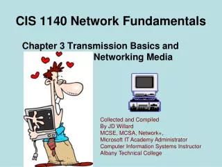
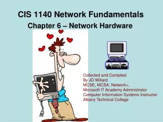
CIS 1140 Network Fundamentals. Chapter 5 – Topologies and Ethernet Standards. Collected and Compiled By JD Willard MCSE, MCSA, Network+, Microsoft IT Academy Administrator Computer Information Systems Instructor Albany Technical College. Attention: Accessing Demos.

E N D
CIS 1140 Network Fundamentals Chapter 5 – Topologies and Ethernet Standards Collected and Compiled By JD Willard MCSE, MCSA, Network+, Microsoft IT Academy Administrator Computer Information Systems Instructor Albany Technical College
Attention: Accessing Demos • This course presents many demos. • The Demosrequire that you be logged in to the Virtual Technical College web site when you click on them to run. • To access and log in to the Virtual Technical College web site: • To access the site type www.vtc.com in the url window • Log in using the username: CIS 1140 or ATCStudent1 • Enter the password: student (case sensitive) • If you should click on the demo link and you get an Access Denied it is because you have not logged in to vtc.com or you need to log out and log back in. • If you should click on the demo link and you are taken to the VTC.com web site page you should do a search in the search box for the CompTIA Network+ (2009 Objectives) Course and run the video from within that page.
Objectives • Describe the basic and hybrid LAN physical topologies, and their uses, advantages, and disadvantages • Describe the backbone structures that form the foundation for most networks • Compare the different types of switching used in data transmission • Explain how nodes on Ethernet networks share a communications channel • Identify the characteristics of several Ethernet standards
Network Topologies • Topology is the term used to describe how devices are connected and how messages flow from device to device • There are two types of network topologies: • Physical topology is the physical layout of the network, including cable and device configuration • Logical topology refers to the method used to communicate between the devices • It is important to understand the physical topology before designing networks, because they can affect the logical topology chosen, how the building is cabled, and what kind of media is used Network Topology Basics Demo
Simple Physical Topologies • Physical topology • Physical layout of nodes on a network • Depicts broad scope • Does not specify: • Device types • Connectivity methods • Addressing schemes • Topology integral to type of network, cabling infrastructure, and transmission media used • Fundamental shapes • Bus, ring, star • Hybrid Physical Topologies Demo
Topologies pt. 1Demo Topologies pt. 2Demo
Bus Bus Topology Demo • Bus topology • Single cable • The single cable is called the bus and supports one channel, where each node shares total capacity • Connects all network nodes • No intervening connectivity devices • One shared communication channel • Physical medium • Coaxial cable • Passive topology • Node listens for, accepts data • Uses broadcast to send
Basic Ethernet Bus • An Ethernet network where all machines are daisy chained using coaxial cable (Thin Ethernet/Thin-net or Thick Ethernet/Thick-net). • Machine 2 wants to send a message to machine 4. • First it 'listens' to make sure no one else is using the network. • If it is all clear it starts to transmit its data on to the network (represented by the yellow flashing screens). • Each packet of data contains the destination address, the senders address, and of course the data to be transmitted. • The signal moves down the cable and is received by every machine on the network but because it is only addressed to number 4, the other machines ignore it. • Machine 4 then sends a message back to number 2 acknowledging receipt of the data (represented by the purple flashing screens).
Terminators • Bus requires a terminator at each end of cable • 50-ohm resistors • Stop signal at end of wire • Prevents signal bounce • Signal bounce • Signal travels endlessly between two network ends • One end grounded • Removes static electricity A terminated bus topology network
Bus (cont’d.) • Bus topology advantage • Easy to install and add devices • Relatively inexpensive • Requires less cable • Disadvantages • Requires 50 ohm terminators at each end of the cable • Requires grounding loop • Does not scale well • Difficult to troubleshoot • Not very fault tolerant • Entire network shuts down if the cable breaks (signal bounce)
Ring Ring Topology Demo • Ring topology • Node connects to nearest two nodes • Circular network • Clockwise data transmission • One direction (unidirectional) around ring • Token passing • Token Ring and FDDI networks • Active topology • Workstation participates in data delivery • Data stops at destination • Physical medium • Twisted pair or fiber-optic cabling
Ring (cont’d.) • Ring advantages • No network collisions • Drawbacks • Malfunctioning workstation can disable network • Not very flexible or scalable A ring topology network
Star Star Topology Demo • Star topology • Node connects through central device • Hub, Router or switch • Physical medium • Twisted pair or fiber-optic cabling • Single cable connects only two devices A star topology network
Star • Most popular fundamental layout • Modern Ethernet networks based on star topology • 1024 addressable logical network nodes maximum How Ethenet accesses the cable and transmits using a hub.
Star (cont’d.) • Star advantages • Fault tolerant • Easier to troubleshoot • A break in the cable does not shut down the network • Higher reliability • Flexible • No terminators required • Star disadvantages • Uses more cable than ring or bus networks • Connectivity devices more expensive than terminators • Connectivity device failures take down entire LAN segments Any single cable connects only two devices, Cabling problems affect two nodes at most
Hybrid Topologies • Pure bus, ring, star topologies • Rarely exist because too restrictive • Hybrid topology • More likely • Complex combination of pure topologies • Several options Hybrid Topology Demo Hybrid Topologies Demo
Star-Wired Ring • Star-wired ring topology • Star physical topology • Ring logical topology • Token passing data transmission method • Benefit • Star fault tolerance • Reliability of token passing • Network use • Token Ring networks • IEEE 802.5
Star-Wired Ring (cont’d.) • Token Ring MAUs can be connected together using straight-through patch cables to connect the Ring Out port of one MAU and the Ring In port of the next MAU until the network of MAUs forms a circle. • Up to 255 stations can be connected to the network when using Shielded Twisted Pair cable and 72 when using Unshielded Twisted Pair cable.
MAU Showing Internal Ring • A Token Ring hub (MAU) changes the topology from a physical ring to a star wired ring. • MAU can automatically bypass any ports that are disconnected or have a cabling fault.
Star-Wired Bus • Star-wired bus topology • Workstation groups • Star-connected devices • Networked via single bus • Advantage • Cover longer distances • Easily interconnect, isolate different segments • Drawback • Cabling, connectivity device expense • Basis for modern Ethernet networks
Star-Wired Bus (cont’d.) A star-wired bus topology network
Logical Topologies • Logical topology: how data is transmitted between nodes • May not match physical topology • Bus logical topology: signals travel from one network device to all other devices on network • Required by bus, star, star-wired physical topologies • Ring logical topology: signals follow circular path between sender and receiver • Required by ring, star-wired ring topologies • Broadcast domain • All nodes connected to single repeating device or switch Logical Topologies Demo
Backbone Networks • Cabling connecting hubs, switches, routers • More throughput • Large organizations • Fiber-optic backbone • Cat 5 or better for hubs, switches • Enterprise-wide network backbones • Complex, difficult to plan • Enterprise • Entire organization • Significant building block: backbone
Serial Backbone • Simplest backbone • Two or more devices • Connect using single medium in daisy-chain fashion • Daisy-chain • Linked series of devices • Benefit • Logical growth solution • Modular additions • Low-cost LAN infrastructure expansion • Easily attach switches
Serial Backbone (cont’d.) • Backbone components • Gateways, routers, switches • Serial connection of repeating devices • Limited distance spanned between each • Standards • Define number of repeating devices allowed • Exceed standards • Intermittent, unpredictable data transmission errors • Not used in modern networks
Distributed Backbone • Connectivity devices • Connected to hierarchy of central connectivity devices • Benefit • Simple expansion, limited capital outlay • More complicated distributed backbone • Connects multiple LANs, LAN segments using routers • Additional benefits • Workgroup segregation • May include daisy-chain linked repeating devices • Consider length • Drawback • Potential for single failure points
Collapsed Backbone • Uses router or switch • Single central connection point for multiple subnetworks • Highest layer • Single router or switch with multiprocessors • Central router failure risk • Routers may slow transmission • Advantages • Interconnect different subnetwork types • Central management
Parallel Backbone • Most robust network backbone • More than one central router, switch • Connects to each network segment • Requires duplicate connections between connectivity devices • Advantage • Redundant links • Increased performance • Better fault tolerance
Switching • Logical network topology component • Determines connection creation between nodes • Three methods • Circuit switching • Packet switching • Multiprotocol label switching Circuit Switching and Packet Switching (3:30)
Circuit Switching • Connection established between two network nodes • Before transmitting data • Dedicated bandwidth • Data follows same initial path selected by switch • Monopolizes bandwidth while connected • Resource wasted • Uses • Live audio, videoconferencing • Traditional telephone calls • Most popular
Packet Switching • Breaks data into packets before transporting • Packets • Travel any network path to destination • Find fastest circuit available at any instant • Need not follow each other • Need not arrive in sequence • Reassembled at destination • Requires speedy connections for live audio, video transmission • Examples • Ethernet networks • Internet
MPLS (Multiprotocol Label Switching) • Introduced by IETF in 1999 • Enables multiple types of Layer 3 protocols: • To travel over any one of several Layer 2 protocols • Most often supports IP • Common use • Layer 2 WAN protocols • Offers potentially faster transmission than packet- or circuit-switched networks • Advantages • Use packet-switched technologies over traditionally circuit switched networks • Create end-to-end paths • Addresses traditional packet switching limitations • Better QoS (quality of service)
Ethernet • Most popular networking technology used on modern LANs • Benefits • Flexible • Can run on various network media • Excellent throughput • Reasonable cost • All variations • Share common access method • CSMA/CD What is Ethernet? Demo Ethernet Demo
CSMA/CD (Carrier Sense Multiple Access with Collision Detection) CSMA / CD Demo • Network access method • Controls how nodes access communications channel • Necessary to share finite bandwidth • Carrier sense • Ethernet NICs listen, wait until free channel detected • Multiple access • Ethernet nodes simultaneously monitor traffic, access media CSMA/CD Access Method demo
CSMA/CD (cont’d.) • Collision • Two nodes simultaneously: • Check channel, determine it is free, begin transmission • Collision detection • Manner nodes respond to collision • Requires collision detection routine • Enacted if node detects collision • Jamming • NIC issues 32-bit sequence • Indicates previous message faulty
CSMA/CD (cont’d.) • Heavily trafficked network segments • Collisions common • Segment growth • Performance suffers • “Critical mass” number dependencies • Data type and volume regularly transmitted • Collisions corrupt data, truncate data frames • Network must detect and compensate CSMA/CD process CSMA/CD and CSMA/CA (5:33)
CSMA/CD (cont’d.) • Collision domain • Portion of network where collisions occur • Ethernet network design • Repeaters repeat collisions • Result in larger collision domain • Switches and routers • Separate collision domains • Collision domains differ from broadcast domains Broadcast domains and collision domains CollisionDomains Demo
CSMA/CD (cont’d.) • Ethernet cabling distance limitations • Effected by collision domains • Data propagation delay • Data travel time too long • Cannot identify collisions accurately • 100 or 1000 Mbps networks • Three segment maximum connected with two repeating devices • 10 Mbps buses • Five segment maximum connected with four repeating devices
Ethernet Standards for Copper Cable • IEEE Physical layer standards • Specify how signals transmit to media • Differ significantly in signal encoding • Affect maximum throughput, segment length, wiring requirements Ethernet Network Types Demo BASE Terminology Demo Ethernet Topologies (7:32)
Ethernet Standards for Copper Cable (cont’d.) • 10Base-T • 10 represents maximum throughput: 10 Mbps • Base indicates baseband transmission • T stands for twisted pair • Requires CAT3 or higher UTP • Two pairs of wires: transmit and receive • Full-duplex transmission
A 10Base-T network • Follows 5-4-3 rule of networking • Five network segments • Maximum segment length is 100 meters • Four repeating devices (hubs) • Three populated segments maximum
Ethernet Standards for Copper Cable (cont’d.) • 100Base-T (Fast Ethernet) • IEEE 802.3u standard • Similarities with 10Base-T • Baseband transmission, star topology, RJ-45 connectors • 100Base-TX • 100-Mbps throughput over twisted pair • Full-duplex transmission: doubles effective bandwidth Fast Ethernet Demo
A 100Base-T network • Supports three network segments maximum • Connected with two repeating devices • 100 meter segment length limit between nodes
Ethernet Standards for Copper Cable (cont’d.) • 1000Base-T (Gigabit Ethernet) • IEEE 802.3ab standard • 1000 represents 1000 Mbps • Base indicates baseband transmission • T indicates twisted pair wiring • Four pairs of wires in Cat 5 or higher cable • Transmit and receive signals • Data encoding scheme: different from 100Base-T • Standards can be combined • Maximum segment length: 100 meters, one repeater Gigabit Ethernet Demo
Ethernet Standards for Copper Cable (cont’d.) • 10GBase-T • IEEE 802.3an • Pushing limits of twisted pair • Requires Cat 6, 6a, or 7 cabling • Maximum segment length: 100 meters • Benefits • Very fast data transmission • Cheaper than fiber-optic • Uses • Connect network devices • Connect servers, workstations to LAN Even Faster Ethernet Demo
Ethernet Standards for Fiber-Optic Cable • 100Base-FX (Fast Ethernet) • 100-Mbps throughput, baseband, fiber-optic cabling • Multimode fiber containing at least two strands • Half-duplex mode • One strand receives; one strand transmits • 412 meters segment length • Full duplex-mode • Both strands send and receive • 2000 meters segment length • One repeater maximum • IEEE 802.3u standard
Ethernet Standards for Fiber-Optic Cable (cont’d.) • 1000Base-LX (1-Gigabit Ethernet) • IEEE 802.3z standard • 1000: 1000-Mbps throughput • Base: baseband transmission • LX: reliance on 1300 nanometers wavelengths • Longer reach than any other 1-gigabit technology • Single-mode fiber: 5000 meters maximum segment • Multimode fiber: 550 meters maximum segment • One repeater between segments • Excellent choice for long backbones
Ethernet Standards for Fiber-Optic Cable (cont’d.) • 1000Base-SX (1-Gigabit Ethernet) • Differences from 1000Base-LX • Multimode fiber-optic cable (installation less expensive) • Uses short wavelengths (850 nanometers) • Maximum segment length dependencies • Fiber diameter, modal bandwidth used to transmit signals