Download
1 / 22
220 likes | 325 Views
Optimal Power System Control (OPSC). for improved system stability, optimal AGC performance, and improved tie-line control, in interconnected or island operating mode (continental, area, sub-area, mini/micro grids). Sub-area: BCTC Northern Southern Interior Lower Mainland - Interior

E N D
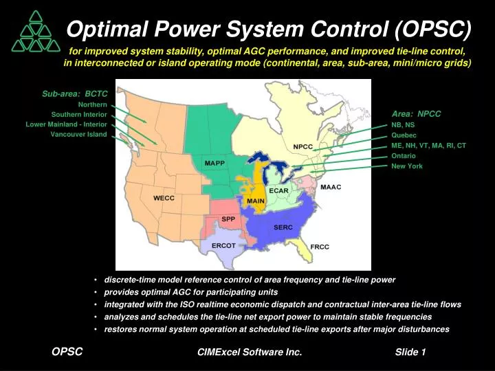
Optimal Power System Control (OPSC) • for improved system stability, optimal AGC performance, and improved tie-line control, • in interconnected or island operating mode (continental, area, sub-area, mini/micro grids) Sub-area: BCTC Northern Southern Interior Lower Mainland - Interior Vancouver Island Area: NPCC NB, NS Quebec ME, NH, VT, MA, RI, CT Ontario New York • discrete-time model reference control of area frequency and tie-line power • provides optimal AGC for participating units • integrated with the ISO realtime economic dispatch and contractual inter-area tie-line flows • analyzes and schedules the tie-line net export power to maintain stable frequencies • restores normal system operation at scheduled tie-line exports after major disturbances OPSCCIMExcel Software Inc. Slide 1
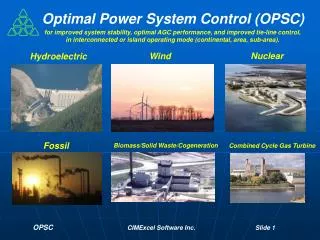
Optimal Power System Control • monitors the power generation from all power plants, and all tie-line power flows • and analyzes the LFC performance of all participating AGC units in the area Nuclear Wind Hydroelectric Fossil Biomass/Solid Waste/Cogeneration Combined Cycle Gas Turbine OPSCCIMExcel Software Inc. Slide 2
Power System Dynamics Model • The ith area is connected to the jth area by the kth tie-line (m areas and n tie-lines) • Mi = inertia of the ith area (s) • ωi = frequency of the ith area (pu) • Gi = generation of the ith area (pu) • D0i = frequency independent load of the ith area (pu) • Di = damping factor of the frequency dependent load of the ith area (pu) • Ei = net export power from the ith area (pu) • Mi d/dt ∆ωi= Gi - D0i - Di ∆ωi - Ei∆ωi = ωi- ωset Ei= ∑p Tp( pth tie-line connected to the ith area ) • calculate Mi and identify Di from a major disturbance. • Formation of multiple internal islands (A,B,C,,, ) with modal area frequencies at the kth discrete-time step: • DA ∆ωA(k+1)= (GA0/γAGi0)(GA(k) - D0A(k)) , with modal area frequencies,∆ωi(k) = αi(GA0DA/Gi0Di) ∆ωA(k) • DB ∆ωB(k+1)= (GB0/γBGi0)(GB(k) - D0B(k)), with modal area frequencies,∆ωi(k) = αi (GB0DB/Gi0Di) ∆ωB(k) • DC ∆ωC(k+1)= (GC0/γCGi0)(GC(k) - D0C(k)), with modal area frequencies,∆ωi(k) = αi (GC0DC/Gi0Di) ∆ωC(k) • Net Export Power Flows: • Ei(k)= Gi(k) - D0i(k) - (GA0/γAGi0)(GA(k) - D0A(k)) ( itharea net export in the Ath island ) • Ei(k)= Gi(k) - D0i(k) - (GB0/γBGi0)(GB(k) - D0B(k)) ( itharea net export in the Bth island ) • Ei(k)= Gi(k) - D0i(k) - (GC0/γCGi0)(GC(k) - D0C(k)) ( itharea net export in the Cth island ) • Tie-line Power Flows: • T= A-1Ewhere A is a r X r matrix (r < s, where s = areas in the internal island). CIMExcel Software Inc. Slide 3
Optimal Power System Control for AGC P1set(j) Optimal AGC Load Allocation OPSC Algorithm Eset net export (inter-area contracts) + PS(j) PAGC(j) APPC power mode Piset(j) Pi(j) ωG set - Pmset(j) ωG(j) pu power setpoints for participating units Enet export(j) l = m+n Filter - Sampler Filter - Sampler • Spinning Reserve • Optimization Modes • uniform • weighted • efficiency • weighted-efficiency ~ 10 seconds ∑ Pl(k) l = m+1 ωG(t) Enet export(t) Filter - Sampler Pm+1(k) Realtime Demand, Import, Export ISO Realtime Economic Load Allocation pu power for non-participating units Pl(k) Pm+n(k) ~ 5 minutes ISO Realtime Pricing Time-of-day Scheduling and Spinning Reserve OPSC CIMExcel Software Inc. Slide 4
Comparison of the Classic and OPSC Approaches for AGC-LFC • Classic Approach • General: • Control of area frequency and tie-line power • 2-4 second update interval • Most Power Plants are in Frequency Control Mode • Participating AGC units with ‘speeder’ before PID • Power Plants do not measure/feedback on power • Power Plants do not achieve the AGC setpoint • Power Generation Monitoring: • None • Demand Monitoring: • Sometimes used for feedforward • Power System Total Power Generation: • Not used for AGC • Optimal AGC Unit Load Allocation: • None • No Spinning Reserve Considerations • Frequency Bias Setting: • Tuned each year • Integral Control Action: • Implicitly with governor ‘speeder’ • Economic Dispatch: • Integrated with ISO functionality • Recovery from Major Disturbances: • Generally not used in automatic mode • Power System Dynamics Model and Simulator: • None • OPSC Approach • General: • Control of area frequency and tie-line power • 10 second update interval - immediate reset on events • Optimal if all Power Plants are in Power Control Mode • Participating AGC units with APPC control algorithms • Power Plants measure/feedback/feedforward on power • Power Plants achieve the AGC setpoint • Power Generation Monitoring: • Each unit with a Power Generation Observer • Demand Monitoring: • Not required for OPSC • Power System Total Power Generation: • Used explicitly for AGC in the OPSC algorithms • Optimal AGC Unit Load Allocation: • Used in the OPSC algorithms (site/units) with 4 modes • 10 second Spinning Reserve Considerations • Frequency Bias Setting: • Set by desired closed loop response of OPSC algorithm • Integral Control Action: • Explicitly at the AGC center - with anti-reset windup • Economic Dispatch: • Integrated with ISO functionality • Recovery from Major Disturbances: • Used in automatic mode • Power System Dynamics Model and Simulator: • Power System Simulator for identification, testing, • and what-if analysis CIMExcel Software Inc. Slide 5
OPSC Performance for a Mini/Micro Grid The generation units for this mini/micro grid include, five 20 MW small hydro units, a 50 MW wind site, a 50 MW biomass cogeneration site, and a 20 MW diesel unit. The demand includes a 100 MW mining site, 50 MW of industrial, and 30 MW of residential. OPSC sends power setpoints to the small hydro units approximately every 10 seconds. The OPSC performance is shown above in response to the significant variations in demand and wind generation. OPSC CIMExcel Software Inc. Slide 6
NERC Sub-Area - (Ontario - IESO) Sub-area: BCTC Northern Southern Interior Lower Mainland - Interior Vancouver Island Area: NPCC NB, NS Quebec ME, NH, VT, MA, RI, CT Ontario (IESO) New York • The generation capacity of this NERC Sub-Area is approximately 30 GW and includes, • Nuclear (10.5 GW) • Coal (5.3 GW) • Gas (CCGT 4.7 GW) • Hydro (7.1 GW) • Wind (1.1 GW) • Other (2.3 GW) • Multiple interconnections with Manitoba, Minnesota, Michigan, New York, and Quebec. • The demand varies in the timeframes, 10 seconds, 5 minutes and 24 hours. OPSCCIMExcel Software Inc. Slide 7
Optimal AGC Load Allocation - NERC Sub-Area OPSC CIMExcel Software Inc. Slide 8
Optimal Power System Control - NERC Sub-Area - AGC Off OPSC CIMExcel Software Inc. Slide 9
Optimal Power System Control – NERC Sub-Area - AGC On • (Hydroelectric sites on AGC – participating units in efficiency optimization mode) OPSC CIMExcel Software Inc. Slide 10
Optimal AGC Load Allocation – Efficiency Mode OPSC CIMExcel Software Inc. Slide 11
Optimal Power System Control – NERC Sub-Area • (AGC On - Export Trip and Recovery) OPSC CIMExcel Software Inc. Slide 12
Optimal Power System Control – NERC Sub-Area • (AGC On - Import Trip and Recovery) OPSC CIMExcel Software Inc. Slide 13
Optimal Power System Control – NERC Areas • Tie-lines CIMExcel Software Inc. Slide 14
Optimal Power System Control – NERC Areas Tie-line and Area Export Schedule 3 Internal Islands are formed as a result of tie-line schedule: • Internal Island A: • ECAR • MACC • NPCC • Internal Island B: • MAIN • MAPP • Internal Island C: • ERCOT • FRCC • SERC • SPP • WECC CIMExcel Software Inc. Slide 15
Optimal Power System Control – NERC Areas • stable area frequencies • are possible for these scheduled tie-line flows • Internal Island A: • ECAR • MACC • NPCC • Internal Island B: • MAIN • MAPP • Internal Island C: • ERCOT • FRCC • SERC • SPP • WECC CIMExcel Software Inc. Slide 16
Optimal Power System Control – NERC Tie-lines CIMExcel Software Inc. Slide 17
Optimal Power System Control – NERC Areas CIMExcel Software Inc. Slide 18
OPSC Analysis and Engineering Services for all Power Plants which participate in AGC for the area (continental, area, sub-area, mini/micro grids) and for all area tie-line power measurement locations, and for the area AGC center. • Analysis • Data Acquisition System setup, interfacing to PLC and systems. • Signal analysis and filtering. • Estimation of the parameters for the Power System Model. • Analysis of the scheduling algorithm for the area tie-line net export power. • Design of the Power Plant AGC-LFC Performance Tests. • Testing • Testing for the Power Plant AGC-LFC Performance. • Baseline Performance monitoring and analysis for interconnected and island operation. • Simulator • Configuration for the Power System Simulator and the OPSC control algorithms. • Comparative Simulation Performance Analysis of existing and OPSC control algorithms. • Integration of the Power System Simulator at the area AGC center. • Installation of the OPSC software • For each AGC Power Plant, install the Power Generation Observer. • For each tie-line location, install the Filtering algorithms. • At the AGC center, in parallel to the existing AGC algorithms with bumpless transfer. • OPSC source code programming and testing. • Performance Trials and Acceptance Testing • Island Mode - AGC response. • Island - Interconnected Transition mode. • Interconnected with Scheduled Tie-line Changes. • Forced Island Mode. • Recovery from Forced Island Mode. CIMExcel Software Inc. Slide 19
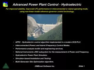
Advanced Power Plant Control (APPC) • for improved stability and improved LFC performance in interconnected or island operating mode • using continuous and discrete-time non-linear model reference control technology. Nuclear Hydroelectric Wind • Steam Turbine Governor • Boiler Pressure and Mass • Reactor Power • PWR, BWR, Areva, CANDU, ACR • Hydraulic Turbine Governor • (Kaplan) Pitch Optimization • Multi-Turbine Optimization • Blade Pitch • Multi-Turbine Optimization Biomass/Solid Waste/Cogeneration Combined Cycle Gas Turbine Fossil • Steam Turbine Governor • Boiler Pressure and Mass • Superheater Temperature • Combustion Control • Burner Management • Steam Turbine Governor • Boiler Pressure and Mass • Multi-Fuel Combustion • Multi-Valve Turbine Flow • Multi-Steam Header • Cogeneration Optimization • Steam Turbine Governor • Boiler Pressure and Mass • Combustor Control • Combined Power CIMExcel Software Inc. Slide 20
Performance Analysis Toolkit High Speed NI-DAQ Signal Processing and Filtering Time Series Analysis Fourier Analysis Power Spectral Analysis CIMExcel Software Inc. Slide 21
Power and Frequency Measurement - Power Generation Observer CIMExcel Software Inc. Slide 22