Download
1 / 48
480 likes | 679 Views
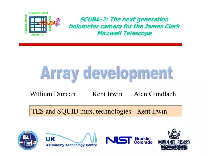
2. SCUBA-2: The next generation bolometer camera for the James Clerk Maxwell Telescope. Array development. William Duncan Kent Irwin Alan Gundlach. TES and SQUID mux. technologies - Kent Irwin. 2. NIST-Boulder Team. Norm Bergren James Chervenak Steve Deiker Erich Grossman Gene Hilton

E N D
2 SCUBA-2: The next generation bolometer camera for the James Clerk Maxwell Telescope Array development William Duncan Kent Irwin Alan Gundlach TES and SQUID mux. technologies - Kent Irwin
2 NIST-Boulder Team Norm Bergren James Chervenak Steve Deiker Erich Grossman Gene Hilton Kent Irwin John Martinis Sae Woo Nam Carl Reintsema Dave Rudman Dave Wollman University of Colorado, Denver Martin Huber
I 0.06 SQUID Amplifier 0.04 Resistance () Vbias 0.02 R(T) TES µcal 0 95.8 96 96.2 Temperature (mK) Voltage-Biased TES 2 Superconducting Transition-Edge Sensor (TES)
Molybdenum-Copper Bilayer 2 Copper Molybdenum • A bilayer of a thin superconducting film and a thin normal metal acts as a single superconductor with a tunable Tc - the “proximity effect” • Molybdenum-copper Robust and temperature stable Molybdenum Tc ~ .92 K Copper normal Substrate 0.06 0.04 Resistance () 0.02 • Sharp • Reproducible <~ 5 mK • Tunable • Robust 0 95.8 96 96.2 Temperature (mK)
2 V P joule V2 R Psink R P sink As the film cools, , and Pjoule increases. Temperature Self-Biasing 2 I Stable equilibrium V SQUID TES Thermometer Temperature Self-Regulation Thermal conductance Heat Sink
9 8 7 6 Current (mA) 5 4 3 2 0.2 0.4 0.6 0.8 1 1.2 1.4 1.6 Voltage (mV) 5 4.5 4 Power (pW) 3.5 3 2.5 2 0 0.05 0.1 0.15 0.2 0.25 0.3 0.35 0.4 Resistance (W) TES I-V I*V is constant here.
Mo-Cu TES on Flyswatter Mo-Cu TES Si3N4 Membrane Empty Space
Fit to theoretical Al oxide K-lines 120 100 Instrument Resolution: 2.0 0.1 eV FWHM Al Ka1,2 80 Counts per 0.25 eV bin 60 40 Al Ka3,4 20 0 1480 1485 1490 1495 1500 1505 Energy (eV)
Fit to theoretical Mn Ka lines 600 Resolution 4.5 0.1 eV FWHM 500 400 Mn Ka1 Counts per 1 eV bin 300 Mn Ka2 200 100 0 5875 5880 5885 5890 5895 5900 5905 5910 Energy (eV)
High Energy Resolution: Resolving Peak Overlaps NIST’s TES x-ray microcalorimeters are now being used to solve critical microanalysis problems for the semiconductor industry, such as contaminant particle identification. NIST’s TES microcalorimeter technology is now being commercialized by multiple companies worldwide
Harvey Moseley Christine Allen Bob Baker Dave Bergman (now at NIST) Rick Shafer NASA/GSFC Team • Invented popup detectors • Leading SPIRE popup detector option effort • Developed Mark II electronics • Co-developing TES on • popup process
Folded PUD and Thermal Bus Bar 1 x 1 mm pixels (Nyquist-sampled for F/5 and l = 350 µm) Bus Bar 1/4 wave Back Short 1 x 5 x 1000 µm legs provide G = 20 pW/K at T= 500 mK
Setup for 1x8 planar TES testing, configured as 2x4 MUX’d array 1x8 Nyquist filter inductors Address resistors (main heat load) SQUIDMUX Chips (4 of 8 channels used) 1x8 planar PUD chip
Ultralow Background Radiometry Assembly Magnetic Shields Cryosource Adiabatic Debagnetization Refrigerator (cold finger hidden)
Thruput : A* = 0.0275 mm2sr (source diameter and 1/8 of cold aperture) Popup Detector Efficiency Measurement
Cryogenic IR Source 100 mK Light Trap with macor baffle tube Emitting Aperature 5.0 mm diam. 4 K Shroud
1.5 NIST R1 TES, pixel 2 1 Measured Efficiency 0.5 Radiometric Efficiency [ P (T ) - P (T )) ] det max det s Expected Efficiency [ P (T ) - P (T ) ] inc max inc s 0 4 5 6 7 8 9 T (K) source Measured Efficiency Source geometry allows some scattered light from source to reach array, increasing measured efficiency. Tests with redesigned source are now being conducted to improve measurement.
2kBT2Gleg 4kBT2Gint CTES Cga Gint Gleg Tbath Thermal Circuit Model of Excess Noise Two parameter fit Gint = 300 GlegConsistent with internal thermal conductance within pud. Cga = CTESConsistent with measured lattice heat capacity of granular aluminum from the literature. -16 10 Green dots: data Red line: Calculated phonon noise NEP (including the effect of electrothermal feedback) NEP(10-17 W/¦Hz) -17 10 0 1 2 10 10 10 Frequency (Hz)
Popup TES Bolometer Noise NIST TES bolometer on a Si popup structure Excess noise eliminated by changing thermal circuit. Tc = 265 mK Pbias = 1.4 pW 1/f knee < 1 Hz bandwidth = 286 Hz NEP = 6 x 10-18 W/rt(Hz) 10-16 NEP (W/rt(Hz)) 10-17 10-18 0.1 1 10 100 1000 Frequency (Hz)
2 Time Division Multiplexing (TDM) Wavelength Division Multiplexing (WDM) Given the constraints on impedance and geometry, TDM is the best way to go on the timescale of SCUBA 2 • look at pixels on one at a time • sample frequency > Nyquist frequency of low pass filter • advantage: turning signal completely off is easy with superconductivity • problem: complexity of digital feedback with switching channels • modulate signal from each pixel into a different waveband • problem: Johnson noise leaking out-of-band Time-Division Multiplexing
2 SQUIDs
Column Flux Bias 2 Column Output Feedback Flux Addr. 1 LIN LFB X X SQUID Output Voltage Input Coil Addr. 2 LFB LIN X X SQUID Bias Current Addr. 3 LIN X X LFB Addr. N LIN X LFB X Addr. N+1 SQUIDs Price of TDM with SQUIDs: must use smart digital feedback which remembers last feedback setting to zero flux
Voltage Bias X X LNYQ RLOAD X X LSA X X LIN LFB X X RTES X X X X LNYQ LIN RTES X X LFB LNYQ LIN RTES LFB X X • Must use series-array SQUID (invented • at NIST) to couple to room-temperature • amplifiers. • Required for high bandwidth and • high dynamic range for switching • feedback operation. • Conventional SQUIDs: impedance • is too low. • Alternative high-bandwidth SQUIDs • (“Additional positive feedback”, and • other techniques to steepen V-phi • curve): dynamic range is too small.
2 Column 2 Column 1 RADD RADD LIN LIN X X X X LFB LFB Row 1 RADD RADD LIN LIN X X X X LFB LFB Row 2 RADD RADD RADD RADD LIN LIN X X X X LFB LFB Row N RADD RADD Two Dimensions of MUX
2 Inductively-Coupled Addressing
Prototype MUX Layout 1 x 8 SQUID multiplexer (one column) 100 SQUID series array
0.08 0.06 0.04 SQUID output (mV) 0.02 0 -0.02 0 0.5 1 1.5 2 Time (ms) MUX Prototype Operational De-Multiplexed Multiplexed Extendable to 200 x 200 arrays with 200 readout channels and 201 address lines
2 Room Temperature Electronics • SQUID MUX Electronics History • “Mark 1” & “Mark 2” electronics: designed and fabricated at NASA/GSFC • with NIST input. Mark 2 capable of MUXing 4 x 8 array with 4 channels. • Address-line drivers designed and fabricated at NIST. • “Rev. 1” electronics: designed and fabricated at NIST. • Developed for ground-based applications • Faster • Cheaper per channel • More on-board signal processing capability • More than x10 lower digital noise into analog circuit • Soon to be interfaced to the address-line driver board
2 Digital Integrator Computer Fiber Optic ADC FPGA DSP DAC Digital Integrator Board Interface Board Electronics Block Diagram Soon to be interfaced to the address line driver board for multiplexing
2 Rev. 1 Electronics are Working
Rev. 1 Field Test There will be a field test of the Rev. 1 electronics with NIST SQUIDs at the McDonald Observatory in December. With a four-channel Stanford optical system, will attempt to measure the pulsar light curve in the optical of Geminga and PSR_B0656+14.
2 How to read out SCUBA-2? • Our arraying scheme must be extensible to the goal of an • 11 arcminutes diameter field at 450 mm (200 x 200 pixels). • Each pixel requires two leads • The pixels cannot be biased in parallel with a common ground • because of constraints on crosstalk and the current sourced to • the base temperature. • Multiplexing outside of the focal plane may be prohibitive. • A 200 x 200 array will require 80,000 leads bump bonded out • of the detector array. It is an immensely difficult wiring, • connectorization, and crosstalk problem to extract these leads • from the focal plane and connect them to 80,000 first-stage • SQUIDs, given constraints on real estate and wafer size.
SQUID wafer (3” diameter) Multiplexing Outside the Focal Plane 6” interconnect wafer Detector Array 11 arcminute diameter (~10 cm) • 80,000 leads, ~1 mm • on 2 mm centers. • Crosstalk and inductance • is an issue. • Complicated bump bonding • problem
2 Detector Array 11 arcminute diameter (10 cm) Multiplexing in the Focal Plane SQUID Wafer • No interconnect wafer • Much smaller total area • Two orders of magnitude • fewer leads • Much simpler bump bonding • Crosstalk and inductance • vastly reduced.
Nyquist Filter Inductor Detector Bias Current SQUID Shunt Resistor Feedback Coil Indium Bump Bonds Multiplexing in the Focal Plane
Address Resistor Address Line Address Lines
Address Resistor Address Line Address Lines
2 Superconducting Ground Plane and Backshort
2 Superconducting Ground Plane and Backshort
2 Bump Bond to Detector Array
2 Bump Bond to Detector Array