Download
1 / 35
360 likes | 558 Views
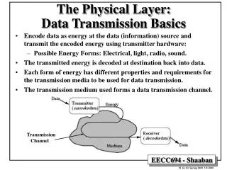
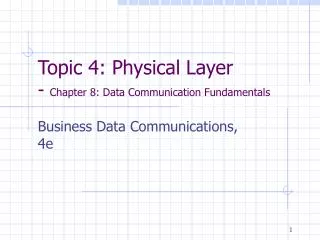
The Physical Layer and Data Communication Fundamentals. Transmission Terminology. Data transmission occurs between transmitter and receiver over some transmission medium.

E N D
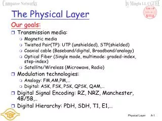
Transmission Terminology • Data transmission occurs between transmitter and receiver over some transmission medium. • Transmission media may be classified as guided or unguided. In both cases, communication is in the form of electromagnetic waves. • Guided media: the waves are guided along a physical path. e.g. • Twisted pair, coaxial cable, and optical fiber • Unguided media: provide a means for transmitting electromagnetic waves but do not guide them. e.g • Air, vacuum, and sea water
Transmission Terminology • Direct link: transmission path between two devices in which signals propagate directly from transmitter to receiver with no intermediate devices, other than amplifiers or repeaters used to increase signal strength. • Point-to-point: first, it provides a direct link between two devices and second, those are the only two devices sharing the medium. Cont…
Transmission Terminology • Multipoint guided configuration: more than two devices share the same medium. • Frequency-domain view of a signal is far more important to an understanding of data transmission than a time-domain view.
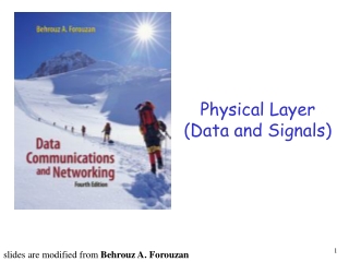
Data Transmission • In transmitting data from a source to a destination, one must be concerned with the nature of the data, the actual physical means used to propagate the data, and what processing may be required. • Analog and digital terms are used frequently in data communications in at least three contexts • Data • Signaling • Transmission
Fundamental Limits of Transmission Media Background Noise • Crosstalk: a signal on one line is picked up by adjacent lines as a small noise signal. It caused when a strong transmitter output signal interferes with a much weaker incoming receiver signal • Impulse noise: caused by external activity or equipment which generates electrical impulses on the line which cause large signal distortion for their duration. • Thermal noise(white noise): caused by the thermal agitation of electrons associated with each atom in the device or transmission line material. It consists of random frequency components of continuously varying amplitude. Cont…
Fundamental Limits of Transmission Media Background Noise • The amount of thermal noise can be found in a bandwidth of 1 Hz in any device. • Noise is assumed to be independent of frequency. • Thermal noise in watts can be found as Cont…
Fundamental Limits of Transmission Media Shannon Channel Capacity • The maximum bit rate of a channel depends on the bandwidth of the channel (W) and the Signal to Noise Ratio (SNR) C=W log2(1+SNR) bits/sec SNR=Avg. Signal Power/Avg. Noise Power Cont…
Fundamental Limits of Transmission Media • Signal Attenuation is the phenomenon whereby the Amplitude of a signal decreases as it propagates along a transmission line. • Attenuation is a function of distance and frequency of signal • Repeaters are used to increase the power of the signal at appropriate intervals • Signal Distortion involves the Shape of the signal becoming altered as it propagates along the line. • One cause of distortion is the different attenuation rates for different frequency components of the signal. • This can be addressed using an equalizer Cont…
Fundamental Limits of Transmission Media • Delay distortion is caused by different frequency components of the signal propagating at slightly different speeds. • If the frequency components of one bit are delayed sufficiently they will overlap with the component of the next bit resulting in Inter Symbol Interference (ISI).
Converting Bits to Signals • Two fundamentally different ways to produce digital signals • DC or lowpass where bits are represented using square waves. • Common encoding schemes include: • Non-return-to-zero (NRZ) • Bipolar • Manchester • Bandpass or modulated where bits are represented using fixed frequency sinusoids. This is used when the channel does not pass low frequency signals. • Common modulation techniques include: • Amplitude shift keying (ASK) • Frequency shift keying (FSK) • Phase shift keying (PSK)
Encoding schemes: Polar Schemes • Polar encoding schemes rely on the voltage level to make a determination of whether a binary 1 or a 0 was sent. • Common Schemes: • Unipolar NRZ: binary 1: +A volts, binary 0: 0 volts. • Polar NRZ: binary 1: +A/2 volts, binary 0: –A/2 volts. • Half the power requirement of unipolar NRZ • Bipolar: Consecutive binary 1s: +/-A/2 volts, binary 0: 0 volts • Produces a frequency spectrum with less low frequency components. • Drawbacks to polar encoding schemes are: • Long strings of either 1s or 0s can cause loss of timing information • Systematic errors in polarity can cause all 1s to be read as 0s and vice versa Cont…
Encoding schemes: Transition Orientated • Manchester encoding: binary 1: transition from A/2 to –A/2 in middle of bit time interval, binary 0: transition from –A/2 to +A/2 in middle of bit time interval. • Differential Manchester encoding: There is a transition at the centre of each bit, but there is only a transition at the start of a 0 bit. • NRZ inverted (NZRI):starting at a fixed signal level, binary 1:denoted by a transition and binary 0: by no transition. • The maximum frequency of a NZRI signal is half that of Bipolar and Manchester encoded signals so it only requires half the transmission bandwidth • Use NRZI in Wide Area Networks (WANs) while the other methods are generally used in LANs. Cont…
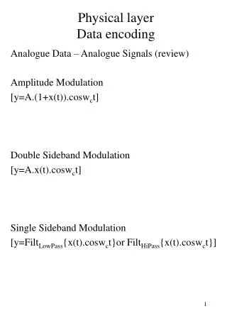
Modulation Schemes • Signaling rate or baud rate is the number of time per sec the amplitude, frequency or phase of the transmitted signal changes. • Amplitude shift keying (ASK):It is the process of varying the amplitude of a carrier wave in proportion to the amplitude of a baseband signal. The frequency of the carrier remains constant • rarely used because of attenuation problems. • Frequency shift keying (FSK):It is the process of varying the frequency of a carrier wave in proportion to the amplitude of a baseband signal. The amplitude of the carrier remains constant • demodulation circuits are simpler. Cont…
Modulation Schemes • Phase shift keying (PSK): complex demodulation circuitry • Uses two fixed signals with a 180 phase difference to each other to indicate a 0 or a 1 respectively • Differential PSK: simple demodulator • Uses a phase shift of 90 relative to the current signal to indicate a binary 0, and a 270 phase shift for binary 1. Cont…
Modulation Schemes • Example of ASK: Representing 1011001010 Digital information Carrier wave ASK modulated signal
Modulation Schemes • Example of FSK: Representing 1011001 Digital information Carrier 1 Carrier 2 FSK modulated signal
Modulation Schemes • Example of Phase Modulation: Representing 10110011 Cont…
Modulation Schemes • Quadrature Phase Shift keying (QPSK): 4 PSK which allows 4 phase changes • Quadrature Amplitude Modulation (QAM): which changes phase and amplitude • The more bits per signal element the higher the throughput is, but the more complex the scheme is. • Bit rate = Baud Rate, where each signal element corresponded to just one bit of data, but more bits per signal element can be encoded. Cont…
Modulation Schemes Quadrature Amplitude Modulation (QAM)
Transmission Modes • Two modes of transmission • Asynchronous • Synchronous. • We will examine bit synchronization for both synchronous and asynchronous transmissions. • It is necessary to determine the start and end of the elements. The technique for doing this is synchronization. • Data streams are often considered to be composed of various elements: • Bits : 0 or 1 • Characters : eight bit sequences • Blocks or frames : potentially variable numbers of bits
Asynchronous Transmission • Used primarily when the data to be transmitted is generated at random intervals. E.g.: a user typing at a keyboard communicating with a computer. • Generally used in applications where the data to be transferred consists of characters, each character being encoded using 7 or 8 binary bits, common coding scheme being ASCII. • As data is transferred randomly there may be long intervals during which no data signal is present on the line. The receiver must be able to resynchronize at the start of each new character received.
Bit Synchronization For Asynchronous Transmission • Each received bit is sampled as near to its centre as possible, to ensure that the correct value is read. • To do this the receiver clock runs at N times the transmitted bit rate, N=16 is typical, ensuring that the received bit will always be sampled close to its centre. • A start bit is required to start clock count.
Disadvantage of Asynchronous Transmission • The use of the start and stop bits for each byte transferred means the method is inefficient in its use of transmission capacity. • The bit synchronization method becomes less reliable as the bit rate increases.
Synchronous Transmission • Used for large blocks of data at higher bit rates. A frame of data is transmitted as a contiguous bit stream with no delay between each 8-bit element. • The receiver clock operates in synchronism with the received signal. • There are two methods of achieving this: • Embedding the clock information into the transmitted signal and having the receiver extract it. • Requires either return to zero or transition orientated scheme. • The receiver keeps a local clock, which is kept synchronized with the received signal using a Digital Phase Lock Loop (DPLL) • May be used for NRZ schemes • Requires sufficient transitions to keep synchronization • Uses bit stuffing (more later)
Media Types • There are number of transmission media types used for Data Communication. The choice of medium depends on: • Distance to be covered • Desired Bite Rate (in bits per second, bps) • Cost Considerations • Media are often categorized as: • Guided • Wireless • Satellite
Guided Media: Two-Wire Open Lines • Used mainly for directly connecting devices • over small distances (< 50 m) and • at moderate bit rates (< 19.2 bps) • Signals get distorted due to: • Crosstalk between the two signals • Susceptibility to Noise Signals from other (external) electrical sources
Guided Media: Twisted Pair Lines • The proximity of signal and reference lines means noise signals are picked up by both wires • Shielded twisted pairs offer better noise immunity • skin effect, which increases attenuation as the bit rate of the transmitted signal increases. • Offer higher bit rates • 1.5 Mbps up to 5 km • 51 Mbps less than 300 m • E.g. high speed data to home (ADSL) and LANs
Guided media: Coaxial Cable • This is made up of an inner conductor surrounded by an insulator and that surrounded again by the outer conductor • Use of the dielectric material and outer conductor effectively isolate the core conductor from external noise interference. • Coaxial cables can be used at rates from over 10Mbps, over distances of several hundred meters. • E.g. Cable TV and Cable Modem
Guided Media: Optical Fiber • Optic fiber does not use electrical signals to transmit the data, rather it uses light. It transmits these signals through thin glass fibers. • Light beams are also immune to electromagnetic interference and crosstalk • Currently up to 40 Gbps with repeaters every 50 km. Theoretically, up to 50 Tbps = 50,000 Gbps. • E.g. access and backbone networks, very fast LANs
Wireless: Terrestrial Microwave/Radio • Provides omnidirectional or unidirectional signalling depending on transmitter and antenna. • Suffer from factors such as bad weather conditions and obstruction by man-made objects. • Use microwaves for large distances, radio waves for shorter distances. Limited by the curvature of the Earth. • E.g. AM and FM radio, TV, Cellular telephony, wireless LANs
Satellite • The first satellites were launched in the 1970’s and now the most common are the Geo-stationary ones at 36,000 km above the Earth. • Satellites are using direct line of sight between the transmitters and receivers. • Data transmitted using electromagnetic (radio) waves propagating through the atmosphere. • Typically many signals will be multiplexed onto a single satellite channel utilizing a high bit rate. • Applications: • Areas with little wired infrastructure • Mobile communication • Broadcast communication • Rapid deployment (military)