Download
1 / 14
140 likes | 151 Views
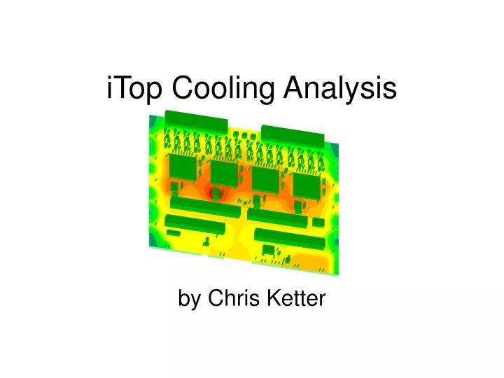
iTop Cooling Analysis. by Chris Ketter. eLog Analysis. Average boardstack temp. 18.6mA each amp. 80.9mA each ASIC. 18.9mA per amp. 106mA per ASIC. With Sanding and Indium. Average board stack temp of all for stacks: 52.7°C Average power consumption of each board: 7.075 W.

E N D
iTop Cooling Analysis by Chris Ketter
eLog Analysis Average boardstack temp 18.6mA each amp 80.9mA each ASIC
18.9mA per amp 106mA per ASIC
With Sanding and Indium Average board stack temp of all for stacks: 52.7°C Average power consumption of each board: 7.075 W
Thermal Simulation • Calculated power consumption of major components • ASIC: .25A@2.5V = .625 W • Amps: 15.5mA@5V = .0775 W each • LT1529: 32*15.5mA@0.6V_drop = .2976 W • LT1963: .25A@0.8V_drop = 0.2 W • Input power dissipations into HyperLynx ThermalSim. Left all other components at default value.
HyperLynx Thermal • Environmental Conditions: • Ambient temp: 25°C • Air velocity: 0 • Sink: left and right edge • Sink temp: 31°C (eLog729 says “entire stack about 6C warmer than cold plate.”) • Therm. Res. of sink = 6.02 (°C-in/W)---calculated from eLog729 • Location: in rack, w/adjacent boards of emissivity of 0.65(default), .356” apart, all dissipating 3.51W. 47.9 53.3 48.8 46.5
Further Considerations • Noticed carrier02 RevD has several dark-looking vias on board edges. Inspected under microscope and found that many (30-40%) of the cooling vias were not properly filled with copper. • Checked carrier13 RevD, and 3 “fake” RevE carriers and did not find same issue. I’m curious as to how many other carrier boards have this same issue.
Pre-Conclusions • It appears that the one-time high temperature of 71°C in eLog707 had poor thermal contact between the carrier boards and aluminum walls, temperatures came down significantly after the HV boards were sanded (eLog728). • Even so, boards were still running too hot. Need further thermal analyses prior to production of RevE carrier board.
Carrier RevE Thermal Model • Board changes: • High power density parts have been moved to board edge • power/GND planes increased to 1.5oz Cu • blind vias utilized to prevent “Swiss cheesing” of inner layers. • Thermal model improvements: • Package sizes refined to include nominal air gaps, thermal pads, and pin dimensions. • Thermal conductivity of aluminum sidewalls changed from calculated value to that of aluminum. • Thermal screw placement evaluated
As Is (Using 4 Different FPGA Powers) MAX 75% 50% 25%
With Thermal Screws 2 4 8 6
30 Oct Update New thermal resistances of sinks added and FPGA thermal pad modeled. (FPGA at 7 W) New Old
Summary • Recall that this model was based on 31 degree aluminum sidewalls, and thermal screws were defined at that same temperature. • Using FPGA at 50% of max power consumption, Tmax = 41.1°C ; T – Tsink = 10.1°C • 2 screws: Tmax = 38.9°C ; T – Tsink = 7.9°C • 4 screws: Tmax = 37.1°C ; T – Tsink = 6.1°C • 6 screws: Tmax = 35.3°C ; T – Tsink = 4.3°C • 8 screws: Tmax = 34.3°C ; T – Tsink = 3.3°C