Download
1 / 70
700 likes | 838 Views
ITEC 275 Computer Networks – Switching, Routing, and WANs. Week 9 Robert D’Andrea. Some slides provide by Priscilla Oppenheimer and used with permission. Agenda. Subnetting Learning Activities Network Management Processes Network Management Architectures

E N D
ITEC 275 Computer Networks – Switching, Routing, and WANs Week 9 Robert D’Andrea Some slides provide by Priscilla Oppenheimer and used with permission
Agenda • Subnetting • Learning Activities • Network Management Processes • Network Management Architectures • Network Management Tools and Protocols • Campus Cabling • Ethernet • Campus Network Design Example
Network Management Processes • International Organization for Standardization (ISO) defines five types of network processes • Fault management • Configuration management • Accounting management • Performance management • Security management
Network Management Processes • Fault management refers to detecting, isolating, diagnosing, and correcting problems. - Develop workarounds - Test workaround - Document workaround in a problem- tracking database - Utilize monitoring tools to alert managers, protocol analyzers and Wire Shark for fault resolution - Syslog network contains timestamp, level, and facility. Syslog severity levels are provided
Network Management Processes • Syslog is a standard for computer message logging. Syslog can be used for computer system management and security auditing as well as generalized informational, analysis, and debugging messages. It is supported by a wide variety of devices (like printers and routers) and receivers across multiple platforms. Because of this, syslog can be used to integrate log data from many different types of systems into a central repository.
Network Management Processes Examples of syslog type files anaconda.syslog boot.log mysqld.log yum.log maillog cron-20140601
Network Management Processes Anaconda is the installation program used by Fedora, Red Hat Enterprise Linux. During an installation, a target computer's hardware is identified and configured and the appropriate file systems for the system's architecture are created. Finally, Anaconda allows the user to install the operating system software on the target computer. Anaconda can also upgrade existing installations of earlier versions of the same distribution. After the installation is complete, you can reboot into your installed system and continue doing customization using the initial setup program.
Network Management Processes • Syslog Levels - Emergency (level 0) - Alert (level 1) - Critical (level 2) - Error (level 3) - Warning (level 4) - Notice (level 5) - Information (level 6) - Debugging (level 7)
Network Management Processes • Syslog Messages - Sent to Cisco router or switch consoles - Sent to Network Management Station - Sent to a remote network host where a syslog analyzer is installed. A syslog analyzer distributes these messages appropriately to the network node manager, and management.
Network Management Processes • Configuration Management helps the network manager maintain a list of devices and information installed on those devices. - Version-logging refers to keeping track of the version of operating systems or applications running on network devices. - Change management includes DHCP and VLAN Trunking Protocol (VTP) automatically updates switches with VLAN information.
Network Management Processes • Accounting management - Facilitates usage-based billing. If not money is exchanged, it identifies consumption and possibly “abuse” of network resources.
Network Management Processes • Performance management - Facilitates measurement of network behavior and effectiveness. -Examine network applications - Protocol behavior - End-to-end performance across an internetwork - Component performance of individual links or devices.
Network Management Processes Security Management allows the network management to maintain and distribute passwords and other authentication information. Security management should also include generating, distributing, and storing encryption keys. • Audit logs should document logins and logouts • Attempts by individuals to change their level of authorization. • Compressing data rather than storing less data
Network Management Architectures • Managed device: Routers, servers, switches, bridges, hubs, end systems, or printers. • Agent: Network management software that resides in a managed device. • Network management system (NMS) is a terminal with software that displays management data, monitor and controls managed devices, and communicates with agents. Typically located in a network operations center (NOC).
Network Management Architectures • In-band monitoring is network management data that travels across an internetwork using the same paths as user traffic. - Impacts ability to trouble shoot problems • Out-of-band monitoring - More complex and expensive - Analog lines are used for backup - Security risks with analog links need a callback mechanisms
Network Management Architectures • Centralized monitoring architecture all NMSs reside in one place of the network • Distributed monitoring means the NMSs and agents are spread out across the entire internetwork. Distributed monitoring involves a more complex network configuration and tends to be harder to manage. • Manage-of-managers (MoM) is a distributed arrangement with a central MNS. The central MNS manages the distributed locations.
Network Management Tools and Protocols • A network management solution should include tools to isolate, diagnose, and report problems and to expedite recovery and quick repair. • Interfaces can be CLI, GUI, and different browsers • SMNPv3 should gradually replace versions 1 and 2 because it offers better security, authentication to protect against modification of information, and secure set operations for the remote configuration od SNMP managed devices.
Network Management Tools and Protocols • Management Information Bases (MIB) stores information from local management agent on a managed device. - Each object in a MIB has a unique identifier. - Network management applications use the identifier to retrieve a specific object. A MIB is a structured tree and hierarchical structure.
Network Management Tools and Protocols The MIB structure is logically represented by a tree hierarchy. The root of the tree is unnamed and splits into three main branches: Consultative Committee for International Telegraph and Telephone (CCITT), International Organization for Standardization (ISO), and joint ISO/CCITT.
Network Management Tools and Protocols These branches and those that fall below each category have short text strings and integers to identify them. Text strings describe object names, while integers allow computer software to create compact, encoded representations of the names. For example, the Cisco MIB variable authAddr is an object name and is denoted by number 5, which is listed at the end of its object identifier number 1.3.6.1.4.1.9.2.1.5.
Network Management Tools and Protocols The object identifier in the Internet MIB hierarchy is the sequence of numeric labels on the nodes along a path from the root to the object. The Internet standard MIB is represented by the object identifier 1.3.6.1.2.1. It also can be expressed as iso.org.dod.internet.mgmt.mib.
Network Management Tools and Protocols • RMON Monitoring (RMON) developed to close the gap in the standard MIBs which lacked the capability to provide statistics on the data link and physical layer parameters. The IETF developed RMON MIB to provide Ethernet traffic statistics and fault diagnosis. - RMON collects CRC errors - Packet-size distribution - Number of packets in and out
Network Management Tools and Protocols - RMON allows the network manager set thresholds for network parameters - RMON configures agents to automatically deliver alerts to NMS. - RMON supports capturing packets and sending the captured packets to the MNS for protocol analysis. - RMON provides information about the health and performance of the network segment.
Network Management Tools and Protocols • Cisco Discovery Protocol (CDP) - Specifies a method for Cisco routers and switches to send configuration information to each other on a regular basis. - CDP runs on the data link layer - Utilizes SNAP - CDP frames are sent every 60 seconds. - - Switches and routers do not forward CDP frames
Network Management Tools and Protocols • Cisco NetFlow Accounting • Collects and measures data as it enters router or switch interfaces. The information enables a network manager to characterize utilization of network and application resources. • Helps network manager visualize traffic patterns so that proactive problems can be detection is possible. • NetFlow allows a network manager to gain a detailed, time-based view of application usage.
Selecting Technologies and Devices • We now know what the network will look like. • We also know what capabilities the network will need. • We are now ready to start picking out technologies and devices. • Chapter 10 has guidelines for campus networks.
Campus Network Design Steps • Develop a cabling plant design • Select the types of cabling • Select the data-link-layer technologies • Select internetworking devices • Meet with vendors
Cabling Plant Design Considerations • Campus and building cabling topologies • The types and lengths of cables between buildings • Within buildings • The location of telecommunications closets and cross-connect rooms • The types and lengths of cables for vertical cabling between floors • The types and lengths of cables for horizontal cabling within floors • The types and lengths of cables for work-area cabling going from telecommunications closets to workstations
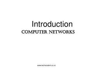
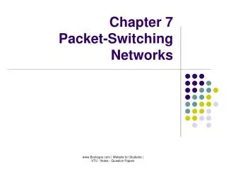
Centralized Versus Distributed Cabling Topologies • A centralized cabling scheme terminates most or all of the cable runs in one area of the design environment. A star topology is an example of a centralized system. • A distributed cabling scheme terminates cable runs throughout the design environment. Ring, bus, and tree topologies are examples of distributed systems.
Building A Centralized Campus Cabling Building B Building C Building D Cable Bundle
Building B Building C Building D Building A Distributed Campus Cabling
Types of Media Used in Campus Networks • Copper media • Optical media • Wireless media
Copper Media Advantages • Conducts electric current well • Does not rust • Can be drawn into thin wires • Easy to shape • Hard to break
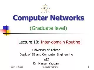
Shielded Twisted-Pair (STP) Copper Media Coaxial Twisted-Pair Unshielded Twisted-Pair (UTP)
Solid copper conductor, surrounded by: Flexible plastic insulation Braided copper shielding Outer jacket Can be run without as many boosts from repeaters, for longer distances between network nodes, than either STP or UTP cable Nonetheless, it’s no longer widely used Coaxial Cable
Twisted-Pair Cabling • A “twisted pair” consists of two copper conductors twisted together • Each conductor has plastic insulation • Shielded Twisted Pair (STP) • Has metal foil or braided-mesh covering that encases each pair • Unshielded Twisted Pair (UTP) • No metal foil or braided-mesh covering around pairs, so it’s less expensive
UTP Categories • Category 1. Used for voice communication • Category 2. Used for voice and data, up to 4 Mbps • Category 3. Used for data, up to 10 Mbps • Required to have at least 3 twists per foot • Standard cable for most telephone systems • Also used in 10-Mbps Ethernet (10Base-T Ethernet) • Category 4. Used for data, up to 16 Mbps • Must also have at least 3 twists per foot as well as other features • Category 5. Used for data, up to 100 Mbps • Must have 3 twists per inch! • Category 5e. Used in Gigabit Ethernet • Category 6. Used in Gigabit Ethernet and future technologies
Types of Cables • Mode is an allowable path for light to travel down a fiber. • Multimode fiber has multiple modes or paths that light can follow. All paths are not equal. some are longer, and the time it takes to travel down each path more time consuming. • Single mode contains a small core diameter, has one path, supports higher bandwith rate over longer distances.
Optical Media Multimode Fiber (MMF) Single-mode Fiber (SMF)
Copper Vs Fiber-Optic Cabling • Twisted-pair and coax cable transmit network signals in the form of current • Fiber-optic cable transmits network signals in the form of light • Fiber-optic cable is made of glass • Not susceptible to electromagnetic force (EMF) or radio frequency interference • Not as susceptible to attenuation, which means longer cables are possible • Supports very high bandwidth (10 Gbps or greater) • For long distances, fiber costs less than copper
Multimode Single-mode • Smaller core diameter • Less bouncing around; single, focused beam of light • Usually uses LASER source • More expensive • Very long distances • Larger core diameter • Beams of light bounce off cladding in multiple ways • Usually uses LED source • Less expensive • Shorter distances
LED Definition: A light-emitting diode(LED) is a two-lead semiconductor light source. It resembles a basic pn-junction diode, which emits light when activated
Ethernet • STP is shielded twisted pair cabling. • UTP is unshielded twisted pair cabling. Typically found in buildings. Generally , least expensive, lowest transmission capabilities because it is subject to crosstalk, noise, and EMI (Electromagnetic Interference). • Coax cabling was popular in the 1980s and 1990s. Not used or installed as it was in the recent past.
Ethernet • Ethernet is a physical and data link layer standard for the transmission of frames on a LAN. - IEEE802.3 has evolved to support UTP and fiber-optic cabling, and fast transmission speeds. - Gigabit Ethernet is targeted for the core layer on enterprise systems.
Wireless Media • IEEE 802.11a, b, g, n • Laser • Microwave • Cellular • Satellite
Cabling Guidelines • At the access layer use • Copper UTP rated for Category 5 or 5e, unless there is a good reason not to • To future proof the network • Use 5e instead of 5 • Install UTP Category 6 rated cable and terminate the cable with Cat 5 or 5e connectors • Then only the connectors need to be changed to move up in speed • In special cases • Use MMF(Multimode Fiber) for bandwidth intensive applications • Or install fiber along with the copper