Download
1 / 20
200 likes | 313 Views
Density Regime of Complete Detachment and Operational Density Limit in LHD. J. Miyazawa 1) , R. Sakamoto 1) , S. Masuzaki 1) , B.J. Peterson 1) , N. Tamura 1) , M. Goto 1) , M. Shoji 1) , M. Kobayashi 1) , H. Arimoto 2) , K. Kondo 2) , S. Murakami 3) , H. Funaba 1) ,

E N D
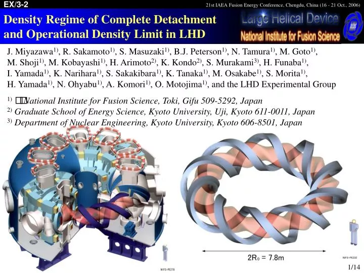
Density Regime of Complete Detachment and Operational Density Limit in LHD J. Miyazawa1), R. Sakamoto1), S. Masuzaki1), B.J. Peterson1), N. Tamura1), M. Goto1), M. Shoji1), M. Kobayashi1), H. Arimoto2), K. Kondo2), S. Murakami3), H. Funaba1), I. Yamada1), K. Narihara1), S. Sakakibara1), K. Tanaka1), M. Osakabe1), S. Morita1), H. Yamada1), N. Ohyabu1), A. Komori1), O. Motojima1), and the LHD Experimental Group 1)National Institute for Fusion Science, Toki, Gifu 509-5292, Japan 2)Graduate School of Energy Science, Kyoto University, Uji, Kyoto 611-0011, Japan 3)Department of Nuclear Engineering, Kyoto University, Kyoto 606-8501, Japan 1/14
Introduction High-density operation in fusion reactor • Future fusion rector will operate in a density range of order 1020 m-3. • Higher density is more favorable, since the fusion reaction rate increases with density squared. • Reduction of divertor heat load by detachment is expected at high-density. High-density experiments in existing devices • High-density plasmas of order1020 m-3 have been studied in medium devices. • Alcator C-Mod tokamak (C-Mod): R = 0.68 m, a = 0.22 m, B 8 T. • Frascati Tokamak Upgrade (FTU): R = 0.935 m, a = 0.31 m, B 8 T. • Wendelstein 7-AS stellarator (W7-AS): R = 2 m, a 0.16 m, B 2.5 T. • Ex) LHD: R = 3.6 m, a = 0.64 m, B 2.75 T (inward-shifted configuration). • Power density in LHD (0.5 MW/m3), is much smaller than in W7-AS ( 4 MW/m3) where volume-averaged density of 4 1020 m-3 was attained with detachment. 2/14
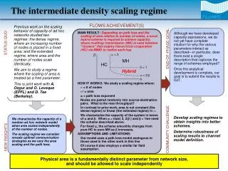
Density limit prediction Density limit of net current free helical plasmas • Sudo density limit scaling (derived from H-E, H-DR, W7A, and L2): ncSudo = 2.5 (PtotB/ (a2 R) )0.5 (units: 1019 m-3, MW, T, and m). e.g. Greenwald Limit : ncGW (1020 m-3) = Ip/(a2) = (5B)/(qaR), … Since the qa scarcely changes in net-current-free plasmas, ncGW is roughly a constant at a given set of B and R (ncGW ~ 1.8 1020 m3, for B = 2.71 T, R = 3.65 m, and qa ~ 0.7). • It has been considered that the power dependence in the Sudo scaling is resulted from the power balance between the heating power and the radiation loss that is proportional to ne2, however, - Radiative collapse is often triggered at a small radiation loss fraction of 30 %. • At complete detachment, the radiation loss fraction ranges from 30 – 100 % without radiative collapse. • Strongly peaked density profile is not within the scope of the Sudo scaling. 3/14
Detachment in LHD Density Radiative Collapse 100eV < 0.8 • Complete Detachment • Plasma column shrinks and Wpdia decreases. • Isat decreases at all the measured divertor tiles. • Marfe • Toroidally axisymmetric radiation belt. • Sustainable in W7-AS. 100eV < 1 • Serpens Mode • Sustainable complete detachment. • A helical radiation belt is formed inside of the LCFS: serpent • The serpent rotates in the EB direction. 100eV ~ 0.9 • Transient Partial Detachment • Localized in the gas puff port. • Without high recycling. • Wpdia slightly decreases. • Hot plasma boundary: 100eV • Radial position where Te = 100±50 eV. • Line radiations from right impurities increase at Te< 100 eV. 100eV > 1 4/14
Complete detachment in gas-fueled plasmas Serpent LCFS (Transient partial detachment) • Isat decreases only in the gas puff port. (Complete detachment) • The hot plasma boundary shrinks below the LCFS (r100eV < 1) and Isat decreases at all the measured divertor tiles. • The density ramp up rate increases even though the gas puff rate is unchanged. Fueling efficiency is improved. (Serpens mode) • r100eV is sustained at ~0.9 • The serpent appears. 5/14
Density regime of complete detachment Pellet-fueled: Attach Detach Gas-fueled: Threshold for complete detachment Threshold for the Serpens mode During the Serpens mode • Density regime of complete detachment is surrounded by the threshold density for complete detachment ( ) and the Serpens mode data ( ). • Radiative collapse takes place above the complete detachment regime. • High-densities in the collapse regime are achieved by applying pellet injection. Collapse regime Complete detachment regime Attachment regime 6/14
Maximum density in pellet-fueled plasmas • <ne> reaches 3 1020 m-3, in spite of small absorbed power density in LHD. • The record ne0 in helical plasmas of 5 1020 m-3 has been achieved in LHD. • A superdense-core (SDC) is formed inside of the internal diffusion barrier (IDB) and the central plasma pressure reaches 1 atm. EX/8-1 N. Ohyabu (on Friday) • These have been achieved in pellet-fueled plasmas with strongly peaked density profiles. 7/14
Edge densities are similar! (Attached data) • Even in the pellet-fueled plasma with a strongly peaked density profile, ne100eV is similar to that of the gas-fueled plasma at the threshold for complete detachment. (Detached data) • ne100eV stays unchanged at various core density. Local densities, ne100eV, at r100eV, are similar for each of attached and detached datasets. 8/14
<ne> linearly increases with the peaking factor Attached data (100eV ~ 1): Gas-fueled Pellet-fueled (Attached data) • In both of gas-fueled and pellet-fueled plasmas, ne100eV are well approximated by 0.8 ncSudo. • Large <ne>in pellet-fueled data is due to the strongly peaked density profile. 9/14
Critical edge density increase with P0.5 Pellet-fueled: Attach Detach Gas-fueled: Threshold for complete detachment Threshold for the Serpens mode During the Serpens mode Collapse threshold Detachment threshold • Critical edge densities for complete detachment and radiative collapse increase with the square root of heating power. • This is also expressed in the Sudo scaling: ncSudo = 2.5 (PtotB/ (a2 R) )0.5. 10/14
Parameter dependence of the edge temperature Attachment regime Critical edge temperature Complete detachment regime • Te at the LCFS is well fitted by (Ptot0.5/ne)2/3, as long as Te > 100 eV. • The critical LCFS density that results in the critical LCFS temperature of 100 eV increases with Ptot0.5. 11/14
Evolution of the edge density • Edge density at a fixed , ne(), increases as the hot plasma column shrinks and 100eV decreases, as long as < 100eV. • Outside 100eV ( > 100eV), ne() decreases with 100eV. • ne100eVis a good representative of the maximum of ne() at each . • 100eV is the radial position inside which one can increase the density by fueling. 12/14
Maximum edge density • ne100eV approximates the maximum local density and increases with Ptot0.5 in the edge region. • A plot of ne100eV / Ptot0.5 versus 100eV corresponds to the radial profile of maximum density in the edge region. • ne100eV / Ptot0.5 in attached plasmas reach the maximum (~ 0.8 ncSudo) at 100eV ~ 1. • ne100eV / Ptot0.5 increases as 100eV decreases and saturates to ~ 1.5 ncSudo. 13/14
Summary • The highest central density in helical plasmas of 5 1020 m-3 has been achieved in LHD. • In pellet-fueled plasmas with strongly peaked density profile. • The volume-averaged density reaches 3 1020 m-3, in spite of small heating power density of < 0.5 MW/m3 and the magnetic field of < 3 T. • Even in these high-density pellet-fueled plasmas, edge densities are similar to those in gas-fueled plasmas with flat or hollow density profiles. • Complete detachment takes place when the edge temperature at LCFS decreases to a critical value of ~100eV (100eV = 1). • In the edge region, the electron temperature is a function of the square root of heating power divided by the electron density. • The critical LCFS density for complete detachment is ~ 0.8 ncSudo. • High edge density of ~ 1.5 ncSudo is sustainable in the Serpens mode plasmas, where the volume-averaged density reaches ~ 2.2 ncSudo . 14/14
The End 15/14
Radiation loss • At the Serpens mode, Prad and the impurity irradiation such as CIII increase. • However, these do not necessarily trigger the transition to the Serpens mode, as seen in the unstable detachment discharge (blue lines in the right figure). • i.e. the unstable detachment discharge does not enter the Serpens mode even though Prad and the CIII intensity exceed the values in the Serpens mode discharge (shown by red lines). • In the unstable detachment discharge, the electron density is lower than the Serpens mode discharge. • Electron density is more important than the total radiation loss. 16/14
Neutral Pressure • The neutral pressure, p0, increases with the edge density in attached plasmas. • At complete detachment, p0 decreases even though gas puffing is continued and the edge density increases. • In the Serpens mode after gas puff turned off, p0 decreases to ~1/3 of that during gas puffing. • Under a low recycling condition, p0 decreases further and reattachment takes place. • Fueling and recycling control is a key to achieve the Serpens mode. 17/14
Maximum <ne> in LHD • The volume averaged electron density (<ne>) exceeds 3 1020 m-3, in spite of small absorbed power density in LHD (< 0.5 MW/m3) compared with W7-AS ( 4 MW/m3) where <ne> = 4 1020 m-3 was attained with detachment. • At the inward shifted configuration (R = 3.65 m). • Attached plasma. • Hollow temperature profile (transient). 18/14
Complete detachment and the Serpens mode Serpent LCFS • At complete detachment, the hot plasma boundary shrinks inside the LCFS. • After the transition to the Serpens mode, complete detachment is sustained with a rotating helical radiation belt, named the serpent. 19/14
Hydrogen recombination • During the Serpens mode, the ratio of Hg /Ha increases to 3 – 5 times of that in the attached phase. • Similar ratio is observed in the detached divertor region and the Marfe radiation belt in W7-AS. • The Hg signal is fluctuating as the Ha signal. • Each of the peaks in Ha and Hg fluctuations appears as the serpent passes by the measurements. • Hydrogen volume recombination in the serpent is suggested. • In this respect, the serpent in LHD and the Marfe in W7-AS resemble each other. 20/14