Download
1 / 18
180 likes | 299 Views
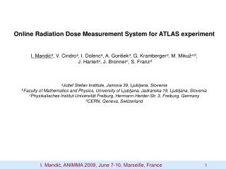
Online Radiation Dose Measurement System for ATLAS experiment I. Mandić a , representing ATLAS collaboration a Jožef Stefan Institute, Jamova 39, Ljubljana, Slovenia. I. Mandić, RAD 2012 , April 25 - 27 , Niš , Srbija 1. The ATLAS experiment.

E N D
Online Radiation Dose Measurement System for ATLAS experiment I. Mandića, representing ATLAS collaboration aJožef Stefan Institute, Jamova 39, Ljubljana, Slovenia I. Mandić, RAD 2012, April25-27, Niš, Srbija 1
The ATLAS experiment • experiment at the Large Hadron Collider at CERN • proton-proton collisions: • in 2011: Ep = 3.5 TeV, Peak Luminosity = 3.6×1033 cm-2s-1 • in 2012: Ep = 4 TeV, Peak Luminosity ~ 6×1033 cm-2s-1 • after 2014:Ep = 7 TeV, Luminosity ~ 1034cm-2s-1 p p I. Mandić, RAD 2012, April25-27, Niš, Srbija2
Radiation Field in ATLAS • secondary particles from p-p interaction point - mostly pions • radiation from interaction of secondary particles with detector material - neutrons • Expected radiation levels: • Total Ionizing Dose (TID): • TID > 100 kGy • Displacement damage caused by • Non Ionizing Energy Loss (NIEL): • Φeq> 1015 n/cm2 • (1 MeV equivalent neutrons in Si) • Thermal neutrons Φ ~ 1015n/cm2 • such radiation levels cause damage to • detectors and readout electronics • Aim of radiation monitoring system: • dose monitoring necessary to understand detector performance • cross check of simulations and make predictions I. Mandić, RAD 2012, April25-27, Niš, Srbija3
TID measurementswithRadFETs • RadFETs: p-MOS transistor • holes caused by radiation get trapped • in the gate oxide: • increase of threshold voltage with dose: • ΔV = a x (TID)b • sensitivity and dynamic range depend on • oxide thickness: Inner detector (highdoses): • 3 RadFETs at each monitoring location: LAAS 1.6 µm; REM 0.25 µm; REM 0.13 µm Other locations (lower doses): • LAAS 1.6 µm LAAS, 1.6 µm REM, 0.25 µm • characterizations, selection, calibrations done by CERN RADMON team: • F. Ravotti, M. Glaser, M. Moll.... (F. Ravotti, PhDthesis, CERN-THESIS-2007-013) I. Mandić, RAD 2012, April25-27, Niš, Srbija4
Displacement damage measurements with diodes • displacement damage expressed in units of equivalent fluence of 1 MeV neutrons • consequences of displacement damage (Non Ionising Energy Loss NIEL) in silicon: • increased resistance, reduced carrier lifetime, increased reverse current … • Two methods for measurements with diodes: • forward bias: voltage at given forward current increases • reverse bias: increasedreverse current Forward bias • linear response ΔV = k ·Φeq • high sensitivity diode (CMRP, University of Wollongong, AU) 109 to ~1012n/cm2, • commercial silicon PIN photodiode BPW34F 1012 to ~1015n/cm2 CMRP (F. Ravotti at al.) I. Mandić, RAD 2012, April25-27, Niš, Srbija5
Displacement damage measurements with diodes Reverse bias • Reverse current proportional to fluenceΔI=Φeq/αV • 25 µm x 0.5 cm x 0.5 cm pad diode with guard ring structure processed • on epitaxial siliconlayer • thin epitaxial diode can be depleted with Vbias < 30 V also after irradiation • with 1015 n/cm2 • - suitable for fluences from 1011 n/cm2 to 1015 n/cm2 I. Mandić, RAD 2012, April25-27, Niš, Srbija6
Thermal neutrons • bipolar transistors as used in front end ASICs • measure base current at given collector current • monitor status of front end electronics • sensitive to fast and thermal neutrons ΔIb/Ic = keq·Фeq + kth ·Фth ;keq, kthand Фeq known Фth can be determined Response to thermal neutrons (reactor) I. Mandić, RAD 2012, April25-27, Niš, Srbija7
Radiation Monitor Sensor Board (RMSB) Inner Detector • for dose monitoring in the Inner Detector: • - large range of doses • - no access • need many sensors • large temperature variations (5to 20°C) • at some locations • stabilize temperature to 20 ± 1 °C by • heating back side of the ceramic hybrid Thick film resistive layer R = 320 Ω CMRP diode • Radfet package: • 0.25 µm SiO2 • 1.6 µmSiO2 • 0.13 µmSiO2 BPW34 diode Thermistor Bipolar transistors Ceramic hybrid (Al2O3) epi diode 4 cm Back side I. Mandić, RAD 2012, April25-27, Niš, Srbija8
Radiation Monitor Sensor Board (RMSB) Other locations • lower dose ranges • mGy to 10 Gy, 109 to ~1012n/cm2 • no temperature stabilization • correct read out values with known • temperature dependences CMRP diode Thermistor LAAS radfet (1.6 µmSiO2 ) I. Mandić, RAD 2012, April25-27, Niš, Srbija9
Readout • use standard ATLAS Detector Control System components • ELMB: • - 64 ADC channels • - CANbus communication • ELMB-DAC: • - current source, 16 channels (Imax = 20 mA, Umax = 30 V) • sensors are biased only during readout (~ few minutes every hour) • software written in PVSS Cable length ~ 18 m Cable length ~ 100 m I. Mandić, RAD 2012, April25-27, Niš, Srbija10
Readout • Information about accumulated doses available online Detector Control System Screen Shot: I. Mandić, RAD 2012, April25-27, Niš, Srbija11
Monitoring Locations • 14 monitors in the Inner Detector I. Mandić, RAD 2012, April25-27, Niš, Srbija12
Monitoring locations • 48 locations at larger radii • 2 monitors very forward (z = 240 m, r = 0.2 m) Calorimeters: 22 Muon detectors: 16 PP2: 10 I. Mandić, RAD 2012, April25-27, Niš, Srbija13
FLUKA Simulations • More in: • I. Dawson and C. Buttar, ”The radiation environment in the ATLAS inner detector”, Nucl. Inst. Meth. A453,pp. 461-467, 2000. • M. Bosman, I. Dawson, V. Hedberg, M. Shupe, “ATLAS Radiation Background Taskforce Final Summary Document”, • ATL-GEN-2005-001. • I. Dawson et al., “Fluence and dose measurements in the ATLAS inner detector and comparison with simulation.” • ATL-COM INDET-2011-001 • FLUKA particle transport code • PHOJET event generator • simulations done for √ s = 7 TeV assuming a proton-proton inelastic cross section 77.5 mb aspredicted by PHOJET Integrated luminosity is a measure of number of proton-proton collisions Simulated dose (fluence) = simulation factor × integrated luminosity I. Mandić, RAD 2012, April25-27, Niš, Srbija14
Results Inner Detector (ID) • data up to 31st October 2011 • Integrated luminosity ~ 5.6 fb-1 NIEL (1 MeV equivalent neutron fluence) measured with CMRP diodes (high sensitivity, forward bias) TID measured with 0.13 um RadFET (low sensitivity) • averages of measurements with sensors at similar locations are shown • excellent agreement with predictions! I. Mandić, RAD 2012, April25-27, Niš, Srbija15
Results ID • first signs of base current increase in DMILL • bipolar transistors • current increase consistent with thermal • neutron fluence of the order of 1011 n/cm2 in agreement with FLUKA Epitaxial diode Good agreement with reverse current measurements with thin epitaxial diode I. Mandić, RAD 2012, April25-27, Niš, Srbija16
Results out of ID • outside of ID (radius > 2 m) doses still very low, on the limit of sensitivity • accumulated dose proportional to integrated luminosity • neutron fluences too low for reliable measurements I. Mandić, RAD 2012, April25-27, Niš, Srbija17
Summary • online radiation dose measurement system working! • measured doses and fluences proportional to integrated luminosity • in the Inner Detector excellent agreement with predictions from FLUKA simulations • important for prediction of future detector performance • important for upgradedesign • radiation damage already seen in detector components • increase of reverse current in silicon detectors • damage in agreement with FLUKA simulations I. Mandić, RAD 2012, April25-27, Niš, Srbija18