Download
1 / 82
1.57k likes | 3.21k Views
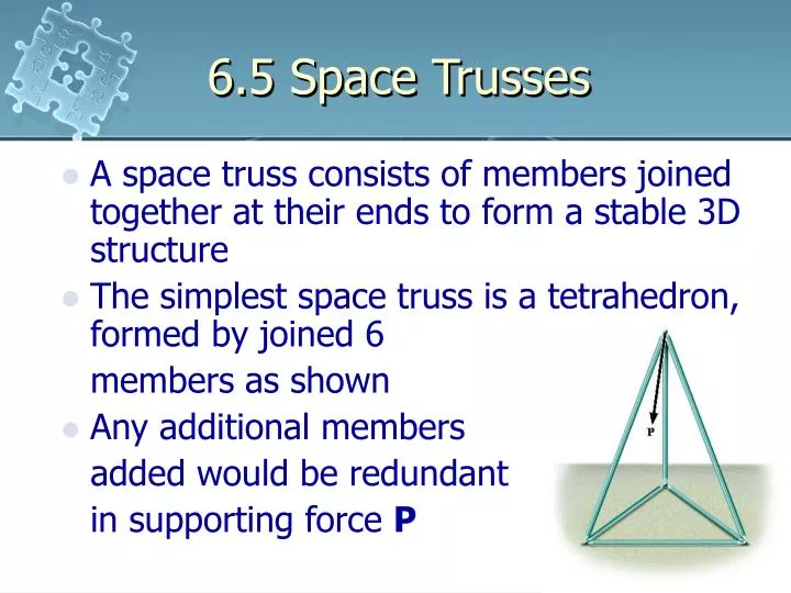
6.5 Space Trusses. A space truss consists of members joined together at their ends to form a stable 3D structure The simplest space truss is a tetrahedron, formed by joined 6 members as shown Any additional members added would be redundant in supporting force P. 6.5 Space Trusses.

E N D
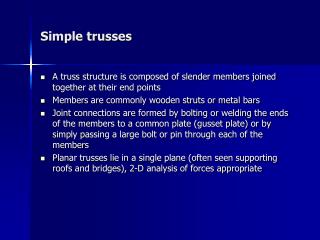
6.5 Space Trusses • A space truss consists of members joined together at their ends to form a stable 3D structure • The simplest space truss is a tetrahedron, formed by joined 6 members as shown • Any additional members added would be redundant in supporting force P
6.5 Space Trusses Assumptions for Design • The members of a space truss may be treated as two force members provided the external loading is applied at the joints and the joints consist of ball and socket connections • If the weight of the member is to be considered, apply it as a vertical force, half of its magnitude applied at each end of the member
6.5 Space Trusses Procedure for Analysis Method of Joints • To determine the forces in all the members of the truss • Solve the three scalar equilibrium ∑Fx = 0, ∑Fy = 0, ∑Fz = 0 at each joint • The force analysis begins at a point having at least one unknown force and at most three unknown forces • Cartesian vector analysis used for 3D
6.5 Space Trusses Procedure for Analysis Method of Sections • Used to determine a few member forces • When an imaginary section is passes through a truss and the truss is separated into two parts, the below equations of equilibrium must be satisfied ∑Fx = 0, ∑Fy = 0, ∑Fz = 0 ∑Mx = 0, ∑My = 0, ∑Mz = 0 • By proper selection, the unknown forces can be determined using a single equilibrium equation
6.5 Space Trusses Example 6.8 Determine the forces acting in the members of the space truss. Indicate whether the members are in tension or compression.
6.5 Space Trusses View Free Body Diagram Solution Joint A
6.5 Space Trusses Solution Joint A To show
6.6 Frames and Machines • Composed of pin-connected multi-force members (subjected to more than two forces) • Frames are stationary and are used to support the loads while machines contain moving parts, designated to transmit and alter the effects of forces • Apply equations of equilibrium to each member to determine the unknown forces
6.6 Frames and Machines Free-Body Diagram • Isolate each part by drawing its outlined shape - show all the forces and the couple moments that act on the part - label or identify each known and unknown force and couple moment with reference to the established x, y and z coordinate system
6.6 Frames and Machines Free-Body Diagram - indicate any dimension used for taking moments - equations of equilibrium are easier to apply when the forces are represented in their rectangular coordinates - sense of any unknown force or moment can be assumed
6.6 Frames and Machines Free-Body Diagram • Identify all the two force members in the structure and represent their FBD as having two equal but opposite collinear forces acting at their points of application • Forces common to any contracting member act with equal magnitudes but opposite sense on the respective members
6.6 Frames and Machines Free-Body Diagram - treat two members as a system of connected members - these forces are internal and are not shown on the FBD - if the FBD of each member is drawn, the forces are external and must be shown on the FBD
6.6 Frames and Machines Example 6.9 For the frame, draw the free-body diagram of • each member, • the pin at B and • the two members connected together.
6.6 Frames and Machines Solution Part (a) • members BA and BC are not two-force members • BC is subjected to 3 forces, the resultant force from pins B and C and the external P • AB is subjected to the resultant forces from the pins at A and B and the external moment M
6.6 Frames and Machines Solution Part (b) • Pin at B is subjected to two forces, force of the member BC on the pin and the force of member AB on the pin • For equilibrium, these forces and respective components must be equal but opposite
6.6 Frames and Machines Solution Part (b) • But Bx and By shown equal and opposite on members AB ad BC results from the equilibrium analysis of the pin rather from Newton’s third law
6.6 Frames and Machines Solution Part (c) • FBD of both connected members without the supporting pins at A and C • Bx and By are not shown since they form equal but opposite collinear pairs of internal forces
6.6 Frames and Machines Solution Part (c) • To be consistent when applying the equilibrium equations, the unknown force components at A and C must act in the same sense • Couple moment M can be applied at any point on the frame to determine reactions at A and C
6.6 Frames and Machines Example 6.10 A constant tension in the conveyor belt is maintained by using the device. Draw the FBD of the frame and the cylinder which supports the belt. The suspended black has a weight of W.
6.6 Frames and Machines Solution • Idealized model of the device • Angle θ assumed known • Tension in the belt is the same on each side of the cylinder since it is free to turn
6.6 Frames and Machines Solution • FBD of the cylinder and the frame • Bx and By provide equal but opposite couple moments on the cylinder • Half of the pin reactions at A act on each side of the frame since pin connections occur on each side
6.6 Frames and Machines Example 6.11 Draw the free-body diagrams of each part of the smooth piston and link mechanism used to crush recycled cans.
6.6 Frames and Machines Solution • Member AB is a two force member • FBD of the parts
6.6 Frames and Machines Solution • Since the pins at B and D connect only two parts together, the forces are equal but opposite on the separate FBD of their connected members • Four components of the force act on the piston: Dx and Dy represent the effects of the pin and Nw is the resultant force of the floor and P is the resultant compressive force caused by can C
6.6 Frames and Machines Example 6.12 For the frame, draw the free-body diagrams of (a) the entire frame including the pulleys and cords, (b) the frame without the pulleys and cords, and (c) each of the pulley.
6.6 Frames and Machines Solution Part (a) • Consider the entire frame, interactions at the points where the pulleys and cords are connected to the frame become pairs of internal forces which cancel each other and not shown on the FBD
6.6 Frames and Machines Solution Part (b) and (c) • When cords and pulleys are removed, their effect on the frame must be shown
6.6 Frames and Machines Example 6.13 Draw the free-body diagrams of the bucket and the vertical boom of the back hoe. The bucket and its content has a weight W. Neglect the weight of the members.
6.6 Frames and Machines Solution • Idealized model of the assembly • Members AB, BC, BE and HI are two force members
6.6 Frames and Machines Solution • FBD of the bucket and boom • Pin C subjected to 2 forces, force of the link BC and force of the boom • Pin at B subjected to three forces, force by the hydraulic cylinder and the forces caused by the link • These forces are related by equation of force equilibrium
6.6 Frames and Machines Equations of Equilibrium • Provided the structure is properly supported and contains no more supports and members than necessary to prevent collapse, the unknown forces at the supports and connections can be determined from the equations of equilibrium • The selection of the FBD for analysis are completely arbitrary and may represent each of the members of the structure, a portion or its entirety.
6.6 Frames and Machines Equations of Equilibrium • Consider the frame in fig (a) • Dismembering the frame in fig (b), equations of equilibrium can be used • FBD of the entire frame in fig (c)
6.6 Frames and Machines Procedures for Analysis FBD • Draw the FBD of the entire structure, a portion or each of its members • Choice is dependent on the most direct solution to the problem • When the FBD of a group of members of a structure is drawn, the forces at the connected parts are internal forces and are not shown • Forces common to two members which are in contact act with equal magnitude but opposite sense on their respective FBD
6.6 Frames and Machines Procedures for Analysis FBD • Two force members, regardless of their shape, have equal but opposite collinear forces acting at the ends of the member • In many cases, the proper sense of the unknown force can be determined by inspection • Otherwise, assume the sense of the unknowns • A couple moment is a free vector and can act on any point of the FBD
6.6 Frames and Machines Procedures for Analysis FBD • A force is a sliding vector and can act at any point along its line of action Equations of Equilibrium • Count the number of unknowns and compare to the number of equilibrium equations available • In 2D, there are 3 equilibrium equations written for each member
6.6 Frames and Machines Procedures for Analysis Equations of Equilibrium • Sum moments about a point that lies at the intersection of the lines of action of as many unknown forces as possible • If the solution of a force or couple moment magnitude is found to be negative, it means the sense of the force is the reserve of that shown on the FBD
6.6 Frames and Machines Example 6.14 Determine the horizontal and vertical components of the force which the pin C exerts on member CB of the frame.
6.6 Frames and Machines Solution Method 1 • Identify member AB as two force member • FBD of the members AB and BC
6.6 Frames and Machines Solution
6.6 Frames and Machines Solution Method 2 • Fail to identify member AB as two force member
6.6 Frames and Machines Solution Member AB
6.6 Frames and Machines Solution Member BC
6.6 Frames and Machines Example 6.15 The compound beam is pin connected at B. Determine the reactions at its support. Neglect its weight and thickness.
6.6 Frames and Machines Solution • FBD of the entire frame • Dismember the beam into two segments since there are 4 unknowns but 3 equations of equilibrium
6.6 Frames and Machines Solution Segment BC
6.6 Frames and Machines Solution Member AB
6.6 Frames and Machines Example 6.16 Determine the horizontal and vertical components of the force which the pin at C exerts on member ABCD of the frame.
6.6 Frames and Machines Solution • Member BC is a two force member • FBD of the entire frame • FBD of each member
6.6 Frames and Machines Solution Entire Frame
6.6 Frames and Machines Solution Member CEF