Download
1 / 15
150 likes | 265 Views
AGW Control System. Jesper Storm, Günter Möstl. The AGW Control Electronics. The general philosophy behind the control system is to have very low power dissipation while observing, to have a robust system (as few connectors as possible), to minimize the

E N D
AGW Control System Jesper Storm, Günter Möstl
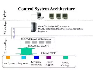
The AGW Control Electronics The general philosophy behind the control system is to have very low power dissipation while observing, to have a robust system (as few connectors as possible), to minimize the space for electronic boxes and to have a high degree of flexibility. This can be realized with Delta Tau's Macro (Motion And Control Ring Optical) system. It allows you to connect multi axis motion controllers, amplifiers and I/O over a single high speed fiber optic network. The Macro Station provides the remote interface for Encoders, Flags, Direct PWM and/or Analog Drives and Digital I/O. The MACRO products are based on the PMAC2 Ultralite family of boards. The VME based PMAC2 UltraLite in combination with the MACRO interface could be seen as a PMAC2 divided in two halves: the central processing portion that contains the DSP processor and the distributed circuitry that connects to motors, amplifiers and different I/O points. The PMAC2 and the MACRO interface are linked with a fiber optic or twisted pair connection. This clever distribution of components brings many benefits: drastic reduction of wiring complexity, elimination of interference by electromagnetic noise and long distance connec- tions (3000 m, ~2 miles with glass fiber). The PMAC2 VME Ultralite can control up to 8 axes.
The VME crate will reside somewhere outside the telescope structure. It will communicate over the optical fibre connection with a smaller UMAC crate installed inside the AGW unit itself. The UMAC box is a modular 3U Eurocard format system, which can host cards for motor axes control, I/O etc. Linear stages and wheels The linear stages for focussing and movement of the off-axis unit will be controlled with DC motors and be equipped with incremental encoders, limit switches as well as electronic end stops. The stages will all be equipped with brakes which will engage when the correct position has been reached. To reduce power disipation the brakes will engage when the power is switched off and similarly the power to motors and power stages will be switched off when the position has been reached. For the filter wheels we have chosen to use stepper motors because they allow us the option of open loop control. Also they do not need a tacho generator, and the brush free motors are highly reliable and need very little maintenance. Movements will be braked when in position with brakes which only dissipate energy while released. We will not have encoders but we will simply count pulses and go over an initialization point for each change of position to ensure that the position does not drift.
On-axis unit The two gimbal mirrors in the pupil plane of the on-axis unit will also be controlled with stepper motors, and they will also have encoders mounted so precise positions can be maintained over long time. The on-axis unit might be equipped with a piezo-actuator tip-tilt mirror in the wavefront sensing arm, to provide a spatially oscilating image for the so called pyramid wavefront sensor. The device will have its own control electronics as provided with the actuator. Software The PMAC controllers will be installed in a VME chassis with a CPU board running under VxWorks. Presently there are no commercial VxWorks drivers for the PMAC but C-routines exists and a development environment under NT is also available where subroutines can be developed if one does not want to develop VxWorks drivers from scratch. These executables can then be called by the VxWorks layer. The idea would be to keep this very low level very simple and leave much of the morecomplicated stuff for the higher VxWorks level. F.ex. the conversion between arcsec and stepper pulses should be maintained at the VxWorks level, but sending a motor 117 pulses will be done at the low level.
We have not yet begun a detailed design of the software as this piece of hardware only came to our attention a couple of months ago. However there seems to be good support (they actually respond to inquiries) and the pieces are readily embedded in the general environment which is foreseen for the TCS. In particular the use of VxWorks and TCP/IP (Remote Procedure Calls, RPC) for the interface to the rest of the system. CCDs The CCDs will be controlled with the SDSU Gen-II controller. The controller will be in-stalled on-board the AGW unit as the cabling cannot be wired across the cable wrap. Two controllers will be needed for each unit, the idea being that the wavefront sensing and guiding can be done in parallel at different frame rates by employing two independent controllers. If the off-axis unit is used, the controllers will be running the off-axis CCDs and when the on-axis unit is in operation they will switch to operate these two detectors. The controllers will be connected to a PCI-bus interface board providing a fast optical fibre link through the cablewrap. This board constitutes the interface to the TCS. STRAP unit If we go for a photon counting system for the tip-tilt guiding, then we would probably choose the STRAP units developed for ESO. They are controlled with a VME computer and a number
of specially designed control boards residing in this computer. The max distance between the VME crate and the detector is 15m, so we are at the limit for going over the cablewrap. This crate is quite large, so it would be a significant advantage to place it outside the unit. DELTA TAU Data Systems, Inc. http://www.deltatau.com/
AGW CONTROL ELECTRONICS (1) AZIMUTH PLATFORM ON BOARD VME UMAC CPU . MACRO (FIBER) Motion Controller 1 MACRO CPU AXIS EXPANSION 1 Motion Controller 2 IE LS, HS AXIS EXPANSION 2 CH 1...12 Amplifier Unit (A1...A12) M 1...12 SO, DI, AE Serial I/O IE AXIS EXPANSION 3 BR PS PSI I/O Device Control Unit LAN RS 232/RS 422 Serial I/O TD Signals and Devices: A: AmplifierAE: Amplifier Enable BR: BrakeCH: Control Channel DI: Direction HS: Home Switch IE: Incremental Encoder LS: Limit Switch Motion Controller: PMAC2-VME Ultralite Axis Expansion: ACC-24E2S (4 Axis Stepper) I/O: ACC-14E (48 TTL-I/O)miniModul: Phytec MiniModul-535 Serial I/O: CXM-SIO3, RS232/RS422/RS485 (PEP) M: DC, Stepper Motor PS: Power Supply PSI: Power Supply Interrupt SO: Step Out
AGW CONTROL ELECTRONICS (2) (10) IE (6) LS, HS CH 1 (5) MD (6) SO, DI, AE M G1x A1 IE PS 1 (2) (2) (2) BR 1 PSI 1 (10) IE (6) LS, HS CH 2 (5) MD (6) SO, DI, AE M G1y A2 IE (2) (2) PS 2 BR 2 (2) PSI 2 (10) IE (6) LS, HS CH 3 (5) MD (6) SO, DI, AE M G2x A3 IE (2) PS 3 BR 3 (2) (2) PSI 3 (10) IE (6) LS, HS CH 4 (5) MD (6) SO, DI, AE M G2y A4 IE (2) (2) BR 4 PS 4 (2) PSI 4 (10) IE (6) LS, HS CH 6 (5) MD (6) SO, DI, AE M X A5 IE (2) (2) PS 5 BR 5 (2) PSI 5 (10) IE (6) LS, HS CH 7 (5) MD (6) SO, DI, AE M Y A6 IE (2) (2) PS 6 BR 6 (2) PSI 6 Amplifier Unit
AGW CONTROL ELECTRONICS (3) IE (10) LS, HS (6) CH 7 (5) MD SO, DI, AE (6) M FA1 A7 IE PS 7 (2) (2) (2) BR 7 PSI 7 (10) IE (6) LS, HS CH 8 (5) MD M FA2 (6) SO, DI, AE A8 IE (2) (2) PS 8 BR 8 (2) PSI 8 (10) IE (6) LS, HS CH 9 (5) MD M FA3 (6) SO, DI, AE A9 IE (2) PS 9 BR 9 (2) (2) PSI 9 (6) HS CH 10 (5) MD (6) M FW1 SO, DI, AE A10 (2) (2) BR 10 PS 10 (2) PSI 10 (6) HS CH 11 (6) (5) MD SO, DI, AE M FW2 A11 (2) (2) PS 11 BR 11 (2) PSI 11 (6) HS MD CH 12 (6) SO, DI, AE M FW3 A12 (2) (2) PS 12 BR 12 (5) (2) PSI 12 PS 1...12 BR 1..12 PSI 1...12 Device Control Unit I/O
DEVICE CONTROL UNIT 1 . . 12 1 . . 12 POWER BR 1...12 1...12 1 . . . . . . 12 1 . . . . . . 12 R E L A Y S PS 1...12 1...12 I/O . 1 . . . . . . 12 1 . . . . . . 12 S T A T U S 1...12 PSI 1...12
VME Components • CPU: T.D. • MOTION • CONTROLLER 1-2: PMAC2-VME Ultralite • Linked with MACRO interface through either a fiber or twisted pair cable. • Control up to 8 axes. • Supports all of the popular controller-to-drive interface standards. • SERIAL I/O: CXM-SIO3 • 3 channels, each configurable RS232/RS422/RS485 • VxWorks supported.
UMAC MACRO • MACRO (Motion And Control Ring Optical) • system allows you to connect multi axis motion controllers, amplifiers and I/O over asingle high speed fiber optic or twisted pair network. • The Macro Station provides the remote interface for Encoders, Flags, Direct PWMand/or Analog Drives and Digital I/O. • UMAC (Universal Motion and Automation Controller) • is a modular PMAC system built with a set of 3U-format Eurocards. • can be populated with a MACRO Interface/CPU board and is remotely connected with the PMAC2 Ultralite board through either a fiber optic or twisted pair cable • boards with axis interface circuitry and/or I/O interface circuitry can be added to the UBUS backplane.
UMAC Components • CPU:MACRO Interface/CPU board • 80 MHz DSP56303, • Connected with the PMAC2 Ultralite through fiber or RS-232 only. • Control of servo axis and I/O. • AXIS EXPANSION 1-3:Stepper/Encoder Interface Board: ACC-24E2S • Provides interface circuitry for 4 channels for stepper and encoder signals. • I/O:48-TTL-I/O Board: ACC-14E • Provides 48 discrete digital I/O points at 5V levels. • RACK, BACKPLANE: 3U format, 10 Slot: 218,5 mm wide by 222,2 mm deep by 132 mm high.