Download
1 / 21
220 likes | 361 Views
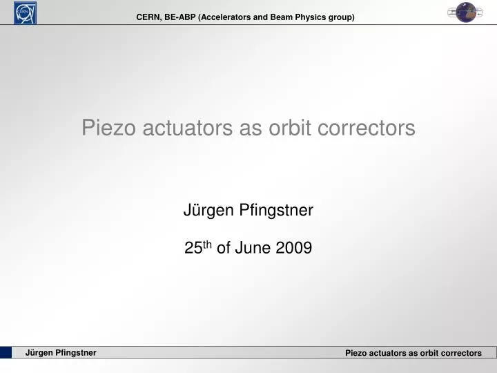
Piezo actuators as orbit correctors. Jürgen Pfingstner 25 th of June 2009. Principle and Motivation. 1.) Corrector coil as orbit corrector. 3.) Actuated quadrupoles as orbit corrector. d. 2.) Action of a displaced quadrupoles. Advantages : Simpler magnet design

E N D
Piezo actuators as orbit correctors Jürgen Pfingstner 25th of June 2009
Principle and Motivation 1.) Corrector coil as orbit corrector 3.) Actuated quadrupoles as orbit corrector d 2.) Action of a displaced quadrupoles • Advantages : • Simpler magnet design • Just one system for Beam- • based feedback and alignment • Cost reduction d d Quadrupole (magnet) Dipole (magnet) Piezo actuator
Math. model of a piezo actuator “Complete” electromechanical model of a piezo cristall [1], [2]: Simple electromechanical model of a piezo cristall [1], [3]: M = mmagnet+ mpiezo_eff Fp Hysteresis Fe Piezo- material k d Fp uin xabs kT qp ← y uin Tem up L+x C xgm up → Fp Fp Fe • Electrical model: • Hysteresis: Assumed to be compensated by feedback • Capacitor: Assumed to be loaded fast enough by amplifier • Mechanical model: • PDE is approximated by a ODE of second order Mechanical model Electrical model
Simplified Model 2nd Newton’s law: State space representation Laplace transformation 2 measurements: y1 … Length of the piezo (xabs – xgm) y2 … vertical acceleration of the magnet ( ) … resonance frequency … damping factor … voltage to length conversion
Piezo amplifier model • In laboratory an amplifier (E-503) from company PI (Physik Instrumente) available • Estimation of the transfer function due to curve in data sheet • Assumption: second order linear system • DC gain of app. 10
Ground motion and noise model Based on the ground motion models of A. Sery and O. Napoly [4]: • Original model not in form that can easily be implemented in Matlab (not a rational tf): • Approximating his model with a few simple transfer functions: 2 low passes of first order, 2 peaks with help of second order function and 2 lead elements. Noise of the sensors: • Two diffenent ground motion model were implemented by noise shaping filters: • LEP model: in quiet conditions (at night and with accelerator turned off) • Hera model: with big cultural noise component (accelerator on) • Capacitive distance sensor: • With measurements in lab: +/- 3nm rms with main component at 200kHz • proper noise filter designed (help of M. Gasior), cutoff at 16 kHz • Accelerometer: • Assumed to be about +/- 1nm rms
Parameter identification Cap. distance sensor E-509 (PI) umeas uin Amplifier E-503 (PI) Piezo act. P-753 (PI) Passive noise filter • Amplifier: • kamp = 11.45 • T1amp = 0.23 ms • T2amp = 0.35 ms • Cap. Distance sensor: • big noise signal • main component around 200kHz • 80mV 80nm • Design and building of a noise filter: • with help from M. Gasior (BE-BI) • second order • passiv • cutoff at app. 16kHz • DC gain 0.929 • Piezo actuator: • kT = 0.67 • = 0.13 • = 2 1538 Hz
System behavior and model verification Remaining meas. noise level : app. 3nm rms Simulation delivers the ‘same’ curves -> Reality and model fit very well
Simulation in Matlab/Simulink • Solver: • variable step size solver • ode45 (Dormain-Prince)
PI controller design • The two poles of the amplifier are dominating. Piezo behavior is damped down • Design by shaping of the open loop: • Wanted form: • Shaping with PI controller • Strategy: • Piezo and amplifier is fast enough • Add integrator • Cancel first pole of the amplifier with the zero • Damp down the system with the factor kp
PI controller results • The PI controller meets the desired specifications of achieving the wanted value within 10 ms. • Measured value y (piezo length) and controlled value x (absolute position) are not the same! White noise on y measurement does not influence control of x. • The actuating signal u does have any overshoot
Scaling piezo behavior for heavy magnet 3.) Piezo amplifier 1.) Resonance frequency of a piezo actuator • According to PI similar than the one in the labratory • Could probably be improved by R&D effort (‘just’ cost) • Assumed to be the same as in laboratory: E-503 The eigenfrequency can be calculated [3] as: … Spring constant of the piezo P-225.40 (high load) … Effective mass of the piezo … Biggest CLIC QP (1.9m) on 3 actuators 2.) Damping factor of a piezo actuator • According to PI for all actuators between 0.2 and 0.1 • Assumed to be the same as for the laboratory model P-753:
Design of the high load piezo controller • Now the piezo behavior is dominating (conjugate complex pole) • A simple PI controller can not correct for that since the w0 is to low to damp down. • Strategy: • Cancel conjugate complex poles with a conjugate complex zeros • Add integrating behavior • Add two roll off poles to make the controller strictly proper • Adjust kp to get the wanted dynamical behavior • Resulting Controller:
Performance of the high load controller • Loop shaping controller meets the specifications without any margin. • The actuating signal has a big overshoot at the amplifier input but not at the piezo input. A piezo amplifier with wider input range could be interesting • With ground motion the design is not sufficient
Feed forward design • More detailed look on the influence of ground motion: gm(t) FF Gd n(t) - - r(t) x(t) y(t) u(t) C + + + + + k - • Transfer function from ground motion to x(t) with feedforward: • Roll off poles have to be added to make FF proper.
Performance of the final strategy • With feed forward strategy, the specifications can be meet, if the sensor signal represents the ground motion well enough. • Interestingly enough the measured signal y the controller acts on has completely different form than the controlled variable x.
Design alternatives investigated • 1.) State controller with Lueneberger observer: • Results in lower actuating signal u at same plant speed • Implementation of feed forward more difficult and not investigated yet (no time) • No integrating behavior • PI State controller would be alternative, but feed forward not directly implementable [6] • 2.) Two degree of freedom controller instead of single feedback and feedforward • Classical approach decouples disturbance rejection and set point following. • The usual design of the feedback for disturbance rejection [5] results in an unstable loop. The reason for that is the unusual action of the disturbance (ground motion) on the measured signal y
Conclusions • The use of a piezo actuated quadrupole as an orbit corrector is possible with the following assumptions made: • The scaling of the small to the big is valid (it is according to piezo company PI). • The ground motion can be accurately measured not only as an acceleration but a displacement in real time (biggest assumtion). • The piezo amplifier should maybe have a bigger input output range to be able to act on fast control action resulting in big actuating signals. But optimization can still be done. • A first design is made which should be further tested and improved (maybe state controller approach is better). • The following influences have not been included in the simulation yet: • Other disturbances than ground motion, that act on the quadrupole directly (sound, electromagnetic fields, cooling water) • Support structure (since no reliable model is available yet)
References • [1] H. Adriaens, W.L. de Koning, and R. Banning. Modeling piezoelectric actuators. IEEE/ASME transactions on mechatronics, 5(4):331–341, 2000. • [2] M. Goldfarb and N. Celanovic. Modeling piezoelectric stack actuators for control of micromanipulation. IEEE Control Systems Magazine, 17(3):69–79, 1997 • [3] PI (Physik Instrumente), http://www.physikinstrumente.com/en/pdf extra/PI designing with piezo actuators tutorial 2005c.pdf. Designing with Piezoelectric Transducers: Nanopositioning Fundamentals, 2005 • [4] Andrey Sery and Olivier Napoly. Influence of ground motion on the time • evolution of beams in linear colliders. Phys. Rev. E, 53:5323, 1996 • [5] Sigurd Skogestad and Ian Postlethwaite. Multivariable Feedback Control: Analysis and Design. Wiley-Interscience, 2005. ISBN: 0-470-01168-8 • [6] Otto Föllinger. Regelungstechnik: Einführung in die Methoden und ihre Anwendung. Hüthig Buch Verlag Heidelberg, 1994. ISBN: 3-7785-2915-3
Sensor signal reconstruction • Fuer naechstes CLIC STA meeting einen zweiten Teil hier (7 Folien (1 Tag Arbeit)): • Grundproblem • Idee zur Signalrueckgewinnung • Ergebnisse eines normalen inversen Filters • Konzept des Blind observers • Ergebnisse • Probleme des Blind Observers • Resume