Download
1 / 48
480 likes | 487 Views
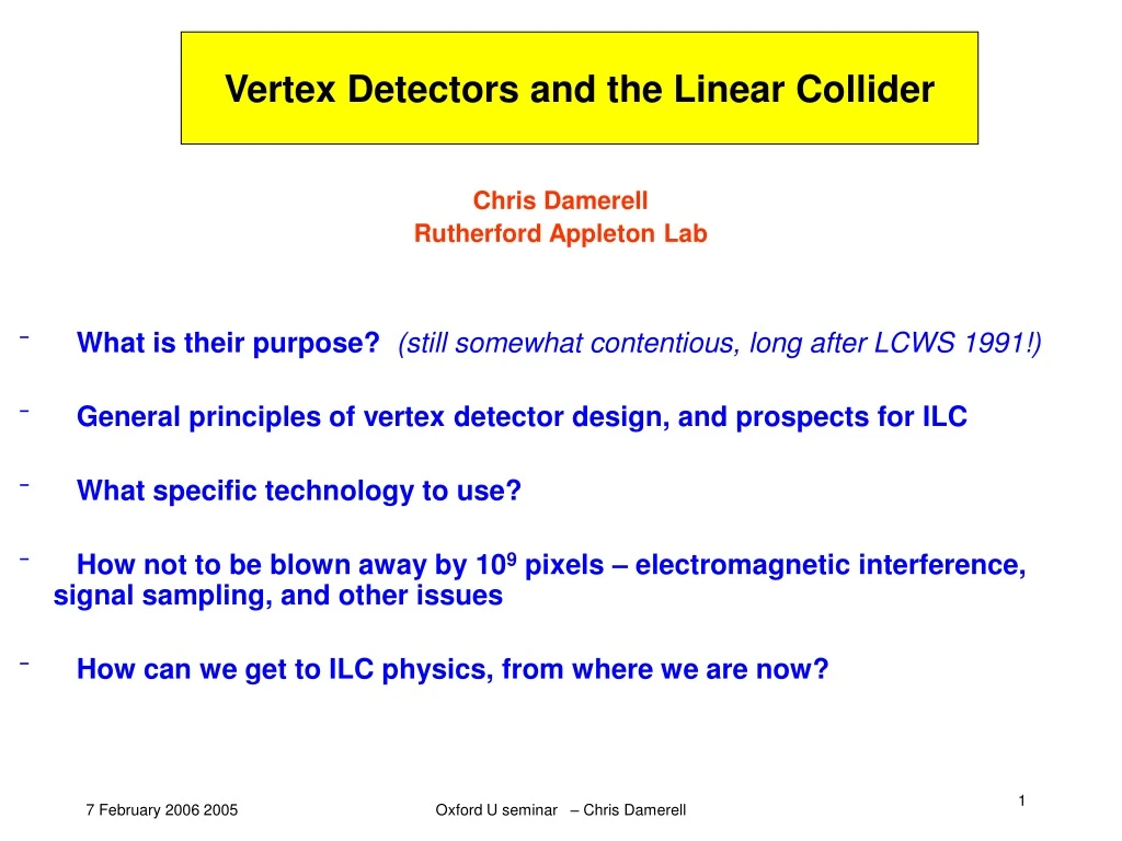
Vertex Detectors and the Linear Collider. Chris Damerell Rutherford Appleton Lab What is their purpose? (still somewhat contentious, long after LCWS 1991!) General principles of vertex detector design, and prospects for ILC What specific technology to use?

E N D
Vertex Detectors and the Linear Collider Chris Damerell Rutherford Appleton Lab • What is their purpose? (still somewhat contentious, long after LCWS 1991!) • General principles of vertex detector design, and prospects for ILC • What specific technology to use? • How not to be blown away by 109 pixels – electromagnetic interference, signal sampling, and other issues • How can we get to ILC physics, from where we are now? Oxford U seminar – Chris Damerell
What are vertex detectors for? • Dave Burke, LCWS 1991 • Particle flow almost reveals the underlying Feynman diagram … Oxford U seminar – Chris Damerell
Vertex detector will tag b and c jets and tau leptons with high efficiency (reducing background, both combinatoric and from other multi-jet processes) • Will also efficiently perform heavy quark sign selection,via measurement of the vertex charge (net charge of tracks in the decay chain) – new from SLD • Consider one important physics example … Oxford U seminar – Chris Damerell
e+e- q qbar differential cross-sections for L and R-polarised electrons at max sqrt(s), as probe of BSM processes • JoAnne Hewett, ‘Indirect Collider Signals for Extra Dimensions’ PRL 82 (1999) 4765 • Sabine Riemann, ‘Fermion-pair production at a linear collider – a sensitive tool for new physics searches’ [LC-TH-2001-007] • Sensitive to Z’, leptoquarks, R-parity violating scalar particles, and extra spatial dimensions Oxford U seminar – Chris Damerell
Restored SU(2)xU(1) Ös ³ 200 GeV electron helicity R L R f- helicity L destructive g-Z interference fwd bbar jet constructive g-Z interference fwd b jet SM leads to strongly fwd peaked differential cross-section (ie, the f- following the e- direction) for either electron helicity, also for an unpolarised electron beam Oxford U seminar – Chris Damerell
Form A(1+z)2 + B(1-z)2 is characteristic of any spin-1 exchange • Unfolding requires clean quark charge sign-selection of the minority population, particularly challenging at large |cos theta| Oxford U seminar – Chris Damerell
96% b-jets 4% bbar jets e-L (e+R) 96% bbar-jets 4% b jets • 40% probability of b quark hadronising to B- , and of bbar hadronising to B+ • ‘Golden’ events (64%) have charged Bs in one or both decay chains* • For these events, vertex charge can unfold the differential cross-section • ‘IP tracks’ create a major challenge. Can in principle clean up by making a decay length cut, but this causes serious loss of sensitivity for rare processes • Studies have barely begun: designated since LCWS 2005 as an important ILC physics benchmark, and it’s good news that Sonja Hillert and Ben Jeffery will carry out a serious study later this year, with tools they are now developing, with valuable advice from Dave Jackson * Case of both decay chains neutral requires more advanced techniques (charge dipole, identified charged kaon or lepton from secondary or tertiary vertex), pioneered in SLD and to be studied later for ILC Oxford U seminar – Chris Damerell
Why is this ‘most basic’ process interesting? • Exchange of gravitons and other virtual heavy particles with spin ¹ 1 wouldlead to (minor) changes in shape of the angular distribution • Sensitivity is enhanced by measurement of ALR in backward region (ie forward bbar jets), where SM cross-sections are small and of very similar magnitude between LH and RH electrons Oxford U seminar – Chris Damerell
Sabine Riemann: one example for large extra dimensions, sqrt(s) = 0.5 TeV Unpol. electrons ALR For these channels, sensitivity extends to MD around 5 TeV for 1 ab-1 For muon pairs, effects are much weaker (not measurable even with this much data) Oxford U seminar – Chris Damerell
Use of vertex charge (much superior to jet charge) was pioneered in SLD: ‘Measurement of parity violation parameters Ab and Ac’, PRL 94 (2005) 091801 • Another example: ‘Measurement of the brancing ratio of the Z into heavy quarks’, SLD Collaboration, PRD74 (2005) 112004 • Procedure has been extended for the ILC by Nicolo de Groot then Sonja Hillert, where the superior vertex detector can yield much enhanced performance • Measurement of vertex charge provides a general tool for unfolding angular correlations and distributions: • Chargino/neutralino angular correlations TESLA TDR (2001) III-64 • Top quark polarisation in e+e- t tbar E Ruiz Morales and M Peskin hep-ph/9909383 • e+e- nu nubar t tbar T Barklow Proc Snowmass 1996 819 • Measurement of top quark polarisation provides numerous applications • These multi-jet processes involve relatively low jet energies, where precision of track measurements is sensitive to multiple scattering effects • Sonja showed that such effects are an important driver for small (12-15 mm) inner layer radius, which was one of the ‘urgent questions’ from the MDI group settled at Snowmass in August 2005 • All 3 detector concepts now set this as their target radius • Meanwhile, what about to the real world … Oxford U seminar – Chris Damerell
General design principles NA32, 1985 • Fixed target experiments were much easier! • For the collider environment, the ‘adequate’ vertex detector has yet to be built – hence numerous options and constant upgrades Oxford U seminar – Chris Damerell
The Founding Fathers – ACCMOR 1980 Missing: Ge Lu, V Ch (taking photo), AG, FW, LL, RE, … Oxford U seminar – Chris Damerell
ACCMOR 1988 Oxford U seminar – Chris Damerell
SLD, thanks to Su Dong Oxford U seminar – Chris Damerell
For the ILC, we can certainly do much better: • Rbp 12-15 mm, cf 25 mm at SLD • Layer thickness 0.05-0.1% X0 , cf 0.4% X0 at SLD [20 mm of Si is 0.02% X0] • Point measurement precision at least as good as at SLD (approx 3 mm) • Resulting impact parameter precision will be mm • Compared with, at SLD: mm mm [really helped by more open geometry, with longer lever arm provided by 5 layers compared to 3] Oxford U seminar – Chris Damerell
Generic long-barrel detector (TESLA TDR) Oxford U seminar – Chris Damerell
SiD vertex detector design concept – Norm Graf Oxford U seminar – Chris Damerell
Measuring flavour ID at ILC Xella Hansen, LCFI, and TESLA TDR ‘Purity’ means for quarks from Z0 decays – it’s only one benchmark Case of charm tag with low light-quark background is interesting, eg for adding flavour tag to reconstructed Ws, to enable top polarization measurement Oxford U seminar – Chris Damerell
Prospects for vertex charge at ILC Hillert: preliminary study. LCFI is now working to provide, for first time, a full set of flavour ID and vertex charge tools for ILC physics. Eagerly awaited by the community Oxford U seminar – Chris Damerell
A vital parameter – the beampipe radius • In 1981, LEP was fixated on a 10 cm RADIUS beampipe … (Villars workshop 1-7 June 1981) • Disappointed, I followed other examples and turned to the New World • ‘SLC? What’s the beampipe radius?’ • ‘About the size of a drinking straw!’ Oxford U seminar – Chris Damerell
Such a time dependence is not inevitable: at LEP it went the other way! • TheirRBP was reduced from 10.6 cm in 1991 to 5.6 cm in 1995 • Maybe the ILC machine design will be a balance between European conservatism, American optimism and Asian realism, hence more stable • In Europe, Nick Walker (ECFA workshop, Obernai, 1999) promised us a radius of 1.5 cm – but not a millimetre less! • Concerns that some high-luminosity option may create excessive background Oxford U seminar – Chris Damerell
What if 10 mm Rbp had been possible at LEP and SLC? • SLD would very probably have measured the Bs mixing parameter – and we are still waiting for that … • At LEP, had they been able to flavour-tag every jet cleanly, would have reached a definitive conclusion about a Higgs boson in their mass range, with only a handful of events, on ZERO background • As with any microscope, getting close helps.The degree of importance for ILC depends on the unknown New Physics, as does the entire project Oxford U seminar – Chris Damerell
What vertex detector technology for the ILC? Technologies Groups CAP/FAPS PNSensor (Munich) CPCCD Bonn U RAL DEPFET Bristol U SLAC FPCCD DESY Strasbourg U ISIS Glasgow U Tohoku Gakuin U MAPS U of Hawaii Toyama College of SoI & 3-D devices Insubria U Maritime Tech Small macropixels KEK AGN-U of Science and Lancaster U Technology, Krakow LBNL Warsaw U Liverpool U Yale U Mannheim U MPI Munich Nijmegen U NIKHEF (Amsterdam) Oregon U Oxford U Recent additions: Fermilab, Washington U, Valencia U, (Edinburgh U) Both lists are probably incomplete – apologies! Oxford U seminar – Chris Damerell
Sensor operating principles 3.2 M-shell plasmons per mm (17 eV) 0.6 L-shell plasmons per mm (120 eV) 0.01 K-shell plasmons per mm (1.5 keV) ~4 primary collisions/mm with wildly fluctuationg energy loss Final thermalisation yields one e-h pair per 3.6 eV deposited Oxford U seminar – Chris Damerell
Minority carrier diffusion length ~ 200 mm ------------------------------ ~ 0.1 mm What epi-layer thickness? Prefer it thin, to avoid losing precision for angled tracks But not too thin, or lose tracking efficiency 20 mm is ‘about right’ • Imagine p and p+ material brought into contact at same potential • Holes pour from p+, leaving a negative space-charge layer (depletion) and forming a positive space charge layer in the p material (accumulation) • This space-charge must of course sum to zero, but it creates a potential difference, which inhibits further diffusion of majority carriers from p+ to p and incidentally inhibits diffusion of minority carriers (electrons) from p to p+ • This barrier is thermally generated, but the ‘penetration coefficient’ is temperature independent, and is simply the ratio of dopant concentrations. eg 0.1/1000, so 10-4 - this interface is an almost perfect mirror! Oxford U seminar – Chris Damerell
We can repeat this on the top surface – here the p-well can be used to implant structures (notably n-channel transistors), ‘monolithic’ with respect to the detector layer below • Positively biased n implants (reverse-biased diodes) serve to collect the signal charges, partly by diffusion, partly by drift in depleted regions created in the p-type epi layer • Overlaying dielectric layers, and photolithographically patterned metal layers complete the toolkit for interconnecting the circuit • Here you have the essentials of a MAPS (monolithic ‘active’ pixels sensor, having transistors within the pixel; in contrast to ‘passive’ CCDs) • To learn about all the beautiful options for ILC vertex detectors, refer to the website of the ILC Detector R&D Panel at https://wiki.lepp.cornell.edu/wws/bin/view/Projects/WebHome Oxford U seminar – Chris Damerell
How not to be blown away by 109 pixels (a) Electromagnetic interference • Electron/positron beams traversing the IR radiate massive RF power (wakefields) • Numerous ‘imperfections’ (thin walled sintered Be beampipe, non-welded flanges, ports for BPMs, kicker magnet circuits, beam-size monitors, vac pumps, …) provide leakage paths for RF • A linear collider is intrinsically more hostile in terms of beam-induced RF than storage rings • The vertex detector (in which ~109 unamplified signal charges of ~1000 e- are transformed to voltage on the gates of tiny transistors within ~1 mm of the beampipe) is more liable to disturbance by this RF than most detector systems • Beam-induced pickup disrupted the SLD vertex detector electronics for several ms after each bunch • Dangerous to assume it will be quieter at a machine with 10 times the energy and 104 times the luminosity of SLC, needing far more instrumentation to preserve its performance • Problems may not be primarily related to RF from the beam – control systems, such as kicker magnet pulsing circuits active during the train may also be dangerous Oxford U seminar – Chris Damerell
Typical example: ideal CCD Oxford U seminar – Chris Damerell
Reality, during the bunch train: From SLD experience, signal charges stored in buried channel are virtually immune to disturbance by pickup. They were transferred in turn to the output node and sensed as voltages between bunches, when the RF had completely died away Could this also be done at ILC? Oxford U seminar – Chris Damerell
Bunch train: 2820 bunches @ 337 ns, every 200 ms • If signals were accumulated throughout a bunch train, background would be totally unacceptable (except maybe for FPCCD of GLC Group) • Seemingly need to read the detector ~20 times during train, at ~50 ms intervals • This may be like trying to hear someone whisper on a railway platform while an express train is roaring by. Why not simply wait? • All detector options considered till recently suffered from this problem • At ECFA workshop in Montpellier, November 2003, a good discussion of CDS etc (Marcel Trimpl et al). Afterwards, we came up with a ‘new idea’ • David Burt of e2V told us ‘It’s been done!’ Even better! Oxford U seminar – Chris Damerell
ISIS: Imaging Sensor with In-situ Storage • Pioneered by W F Kosonocky et al IEEE SSCC 1996, Digest of Technical Papers, p 182 • Current status: T Goji Etoh et al, IEEE ED 50 (2003) 144 • Frame-burst camera operating up to 1 Mfps, seen here cruising along at a mere 100 kfps – dart bursting a balloon • Evolution from 4500 fps sensor developed in 1991, which became the de facto standard high speed camera (Kodak HS4540 and Photron FASTCAM) • International ISIS collaboration now considering evolution to 107 – 108 fps version! Oxford U seminar – Chris Damerell
charge collection to photogate from ~20 mm silicon, mainly by diffusion, as in a conventional CCD • no problems from Lorentz angle • signal charge shifted into storage register every 50ms, to provide required time slicing • string of signal charges is stored during bunch train in a buried channel, avoiding charge-voltage conversion • totally noise-free charge storage, ready for readout in 200 ms of calm conditions between trains • ‘The literature is littered with failed attempts …’ Oxford U seminar – Chris Damerell
Correlated Double Sampling • CDS is a vital part of the strategy to avoid a data deluge, one which most technologies for the ILC vertex detector claim to employ • Even if reading between trains, fluctuations in transistor noise and detector-related pickup sources will be present, as seen at SLD • CDS - term given in early ’70s to pedestal subtraction in CCDs used in astronomy and elsewhere to sense very small signals, where reset noiseand 1/f noise would otherwise have imposed severe performance restrictions • Same functionality was achieved in late ’70s in CCD-based particle detectors, where the sparse data permitted resetting only between rows, hence faster sampling • ERF - Extended Row Filter, was an important refinement added in SLD • ‘Beware of imitations’ Oxford U seminar – Chris Damerell
Baseline settles to a different level after each reset, due to kTC noise ‘uncorrelated double sampling’ ~50 ms Oxford U seminar – Chris Damerell
Extended Row Filter (ERF) suppresses residual noise and pickup: Oxford U seminar – Chris Damerell
SLD experience: Without ERF, rate of trigger pixels would have deluged the DAQ system Read out at 5 MHz, during ‘quiet’ inter-bunch periods of 8 ms duration Origin of the pickup spikes? We have no idea, but not surprising given the electronic activity, reading out other detectors, etc Oxford U seminar – Chris Damerell
How can we get to ILC physics, from where we are now? • Currently many groups are pursuing an expanding range of options for the ILC vertex detector • All use silicon pixels, but there the similarity ends • How to converge on (hopefully) two technologies for two large detectors? • The ILC vertex detector community has informally undertaken to provide working ladders in test beams, circa 2010 (+ d) • Some options will drop out sooner: one has recently done so • Hoping that the self-organising ILC vertex community will themselves converge on the optimal technologies (preferably two) • R&D groups should evaluate their results carefully, considering all performance criteria, including efficiency, spatial resolution, material budget at small angles due to mechanical supports and electronics at ends of ladders, robustness wrt EMI, etc • May need some help from the detector collaborations, to reach decisions … Don’t believe what any of us claim we can deliver! Oxford U seminar – Chris Damerell
Among other things, simulations and R&D will lead to choice between long barrels, short barrels plus forward disks • Everyone who has participated in the R&D should be welcome to join one of the ‘winning’ technologies for detailed design, construction, commissioning, and extracting the physics (ideally, a rerun in miniature of the ITRP process) • Several ‘losers’ will change direction and find wonderful applications for their technologies, and may gain more than they lose! For example, HAPS for LHC, may be at least as important for other applications such as SR detectors (PILATUS, etc) • In the meantime, we continue building a world-wide community who will all enjoy working together • Overall detectorcollaborations should design for convenient access to the vertex and other small-radius equipment for several reasons, including future upgrades. A ‘losing’ technology, could prove to be a long-term winner (as happened with CCDs at SLC) • The SLD vertex detector was considered a ‘jewel in the crown’. This may also be true at ILC – the physics potential, combined with particle flow for jet energy measurement, goes far beyond what can be done at LHC Oxford U seminar – Chris Damerell
Can we be sure that silicon pixels will provide the best solution? • Do you remember the front running technology for SLC in 1982? • CCDs were regarded as a risky outsider. • If you come up with a revolutionary new idea, please do follow it up! Don’t be discouraged by the so-called experts! • In the ’70s, when most expertise in silicon detectors was in the hands of university-based nuclear science people with dirty string-and-sealing wax production facilities, the construction of semiconductor detectors was more like cookery than science … • To these experts, the concept of CCDs as particle detectors seemed outrageous Oxford U seminar – Chris Damerell
SLC Experiments Workshop 1982 Oxford U seminar – Chris Damerell
SOME EXPERT OPINIONS IN 1979 "Put such a delicate device in a beam and you will ruin it". "Will work if you collect holes, not electrons". "Far too slow to be useful in an experiment". "It's already been tried; didn't work". "It will work but only with ≤ 50% efficiency". "To succeed, you will have to learn to custom-build your own CCDs: investment millions". "At room temp it would be easy, but given the need to run cold, the cryogenic problems will be insurmountable". "May work in a lab, but the tiny signals will be lost in the noise (RF pickup etc) in an accelerator environment". However, Wrangy Kandiah from AERE, Veljko Radeka and Pavel Rehak from BNL, Joe Killiany from NRL, Herb Gursky from Harvard Smithsonian, Emilio Gatti from Milano and a few others were supportive Oxford U seminar – Chris Damerell
ILC Detector R&D Panel Measurement of luminosity, beam energy and polarisation (LEP) Vertexing Tracking (gaseous and silicon) Calorimetry (ECAL, HCAL, forward region) Muon tracking Particle ID DAQ systems Electromagnetic interference (EMI) ------------------------------------------------------------------------------------------- Panel members and areas of interest: Jean-Claude Brient: Calorimetry Chris Damerell: Vertexing, EMI, PID Ray Frey: LEP, MDI, calorimetry HongJoo Kim Tracking, calorimetry Wolfgang Lohmann LEP, MDI, tracking, calorimetry Dan Peterson Tracking, PID Yasuhiro Sugimoto Vertexing Tohru Takeshita Calorimetry Harry Weerts Vertexing, tracking, muon tracking Preliminary report was published to WWS-OC on 6 Jan 2006. Hoping it will help correct funding deficiencies in some regions. Future work in liaison with RDB of GDE, aiming to provide gentle guidance to the world-wide R&D programme, specially as it becomes part of an ILC project. During this phase, accelerator R&D is expected to total circa $1 B over 3 years. Oxford U seminar – Chris Damerell