Download
1 / 31
310 likes | 464 Views
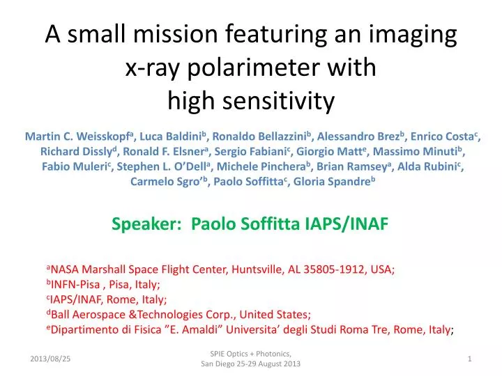
A small mission featuring an imaging x-ray polarimeter with high sensitivity. Speaker: Paolo Soffitta IAPS/INAF. Martin C. Weisskopf a , Luca Baldini b , Ronaldo Bellazzini b , Alessandro Brez b , Enrico Costa c ,

E N D
A small mission featuring an imaging x-ray polarimeter withhigh sensitivity Speaker: Paolo Soffitta IAPS/INAF Martin C. Weisskopfa, Luca Baldinib, Ronaldo Bellazzinib, Alessandro Brezb, Enrico Costac, Richard Disslyd, Ronald F. Elsnera, Sergio Fabianic, Giorgio Matte, Massimo Minutib, Fabio Muleric, Stephen L. O’Della, Michele Pincherab, Brian Ramseya, AldaRubinic, Carmelo Sgro’b, Paolo Soffittac, Gloria Spandreb aNASA Marshall Space Flight Center, Huntsville, AL 35805-1912, USA; bINFN-Pisa , Pisa, Italy; cIAPS/INAF, Rome, Italy; dBallAerospace&Technologies Corp., UnitedStates; eDipartimentodi Fisica ”E. Amaldi” Universita’ degli Studi Roma Tre, Rome, Italy; SPIE Optics + Photonics, San Diego 25-29 August 2013
The situation of X-ray polarimetry today Worse than ever Not only paucity of available data with respect to imaging/timing and spectroscopy but also : GEMS was discontinued for programmatic reason. IXO descooped in Athena and then Athena+ without a polarimeter in the focal plane SPIE Optics + Photonics, San Diego 25-29 August 2013
Do not forget that many years ago ….. SXRP the Stellar X-Ray Polarimeter was part of the Spectrum-X-Gamma mission to be flown in a reasonably short time and While waiting for the results of SRG, any possible mission of polarimetry was hold in stand-by. Kaaret et al., 1989, Tomsick et al., 1997, Soffitta et al., 1998 SPIE Optics + Photonics, San Diego 25-29 August 2013
Thanks to the approval of GEMS and XPOL on IXO, the expectations for new data, have stimulated the theoretical researches on polarimetry. This came out as powerful diagnostic of physics of the inner regions of compact objects and of extreme gravitational and magnetic fields. A number of topics has been also dig on polarimetry as diagnostics of fundamental physics : Strong gravity in galactic black hole & AGN. QED in superstrong B field of magnetars. Quantum Gravity effects. Axion-like-particle search. SPIE Optics + Photonics, San Diego 25-29 August 2013
Some doubts always make expectations from X-ray polarimetry less compelling: • 1. Is the measurement really feasible at the declared level of sensitivity ? • 2. Is the measurement credible ? • 3. Is the measurement meaningful ? Question 1) and 2) are mainly related to the systematic effects. • Any removal of systematic is not for free in terms of statistics. • Background can be an issue for polarimetry of faint sources. Bragg diffraction at 45o around the arrival direction is not very sensitive but has small systematic effects (TBC). SPIE Optics + Photonics, San Diego 25-29 August 2013
Here we present a mission concept based on imaging X-ray polarimetrythat answer to these doubts • X-ray optics with 30’’ of HEW with a high effective area in the 2-6 keV energy band. • A Gas Pixel Detector filled with He-DME based mixture • Imaging possible • Low Background • Small systematics SPIE Optics + Photonics, San Diego 25-29 August 2013
Three light telescopes SPIE Optics + Photonics, San Diego 25-29 August 2013
The detector Gas Pixel Detector Polarimetry - Imaging - Timing - Spectroscopy SPIE Optics + Photonics, San Diego 25-29 August 2013
Modern polarimeters dedicated to X-ray Astronomy exploit the photoelectric effect resolving most of the problems connected with Thomson/Bragg polarimeter. The exploitation of the photoelectric effect was tempted very long ago, but only since five-ten years it was possible to devise photoelectric polarimeters mature for a space mission. An X-ray photon directed along the Z axis with the electric vector along the Y axis, is absorbed by an atom. The photoelectron is ejected at an angle θ (the polar angle) with respect the incidentphotondirection and at an azimuthal angle φ with respect to the electricvector. If the ejected electron is in ‘s’ state (as for the K–shell) the differential cross sectiondepends on cos2 (φ),thereforeitispreferentiallyemitted in the direction of the electricfield. Being the cross sectionalwaysnull for φ = 90o the modulationfactor µ equals 1 for anypolar angle. HeitlerW.,The Quantum Theory of Radiation Costa, Nature, 2001 β =v/c By measuring the angular distribution of the ejected photoelectrons (the modulation curve) it is possible to derive the X-ray polarization. SPIE Optics + Photonics, San Diego 25-29 August 2013
X-raypolarimetry with a Gas Pixel Detector GEM electric field X photon (E) conversion GEM gain collection pixel PCB E a 20 ns The principle of detection To efficiently image the track at energies typical of conventional telescopes IAPS-Rome and INFN-Pisa developed the Gas Pixel detector. The tracks are imaged by using the charge. A photon cross a Beryllium window and it is absorbed in the gas gap, the photoelectron produces a track. The track drifts toward the multiplication stage that is the GEM (Gas Electron Multiplier) which is a kapton foil metallized on both side and perforated by microscopic holes (30 um diameter, 50 um pitch)and it is then collected by the pixellated anode plane that is the upper layer of an ASIC chip. Costa et al., 2001, Bellazzini et al.2006, 2007 Polarization information is derived from the angular distribution of the emission direction of the tracks produced by the photoelectrons. SPIE Optics + Photonics, San Diego 25-29 August 2013 Costa et al., 2001
ASIC features 105600 pixels 50 μm pitch • Peaking time: 3-10 ms, externally adjustable; • Full-scale linear range: 30000 electrons; • Pixel noise: 50 electrons ENC; • Read-out mode: asynchronous or synchronous; • Trigger mode: internal, external or self-trigger; • Read-out clock: up to 10MHz; • Self-trigger threshold: 2200 electrons (10% FS); • Frame rate: up to 10 kHz in self-trigger mode • (event window); • Parallel analog output buffers: 1, 8 or 16; • Access to pixel content: direct (single pixel) or serial • (8-16 clusters, full matrix, region of interest); • Fill fraction (ratio of metal area to active area): 92%) The chip is self-triggered and low noise. It is not necessary to readout the entire chip since it is capable to define the sub-frame that surround the track. The dead time downloading an average of 1000 pixels is 100 time lower with respect to a download of 105 pixel. SPIE Optics + Photonics, San Diego 25-29 August 2013
Tracksreconstruction 1) The track is recorded by the PIXel Imager 2) Baricenter evaluation 3) Reconstruction of the principal axis of the track: maximization of the second moment of charge distribution 4) Reconstruction of the conversion point: major second moment (track length) + third moment along the principal axis (asymmetry of charge release) 5) Reconstruction of emission direction: pixels are weighted according to the distance from conversion point. SPIE Optics + Photonics, San Diego 25-29 August 2013
A new prototype with an extended GEM for better drift field uniformity NEW OLD Samewindow, same ASIC but a muchlarger GEM, with the addition of a large Guard Ring and fieldformingframes. SPIE Optics + Photonics, San Diego 25-29 August 2013
The calibration facility Close-up view of the polarizer and the Gas Pixel Detector Facility at IASF-Rome/INAF keV Crystal Line Bragg angle 1.65 ADP(101) CONT 45.0 2.01 PET(002) CONT 45.0 2.29 Rh(001) Mo Lα 45.3 2.61 Graphite CONT 45.0 3.7 Al(111) Ca Kα 45.9 4.5 CaF2(220) Ti Kα 45.4 5.9 LiF(002) 55Fe 47.6 8.05 Ge(333) Cu Kα45.0 9.7 FLi(420) Au Lα45.1 17.4 Fli(800) Mo Kα44.8 Aluminum and Graphite crystals. Capillary plate (3 cm diameter) Spectrum of the orders of diffraction from the Ti X-ray tube and a PET crystal acquired with a Si-PiN detector by Amptek PET (Muleri et al., SPIE, 2008) SPIE Optics + Photonics, San Diego 25-29 August 2013
Modulation curve at 2.0 keV An X-raypolarimeter with spectroscopiccapabilities Pure DME (CH3)2O μ = 13.5% (Muleri et al., 2010).
The imaging properties of the GPD. Panter X-ray facility (MPE, Germany): JET-X (Telescope, same as Swift, ~1mm/arcmin) Focal Length (3.5 m) JET-X HEW (4.5 keV, 4.5 keV) : 18’’ JET-X + GPD (HEW) : 23.2’’ (394 m ) IAPS/INAF laboratory : Very narrow pencil beam. Detector shifts : 300 m Location accuracy : 30 m (rms) Half Energy Width : 93 m Spiga et al., 2013, Fabiani et al. 2013 Imaging properties are mainly driven by the optics. See Talk 8859-22 :Soffitta et al. tomorrow
Absence of spurious modulation New Design 125 kcounts: Modulation factor: ~50% Spurious modulation measured: ~0.54% Spurious polarization measured: ~1% MDP 99% with m=50% and 125 kc: ~ 2.3% • Check on the control of absence of systematics with Fe55 source at the moment (5.9 keV). Many celestial source are expected to be highly polarized, however : To measure 2 % of polarization (modulation of ~1%) the systematics should be understood/eliminated at level well below 1%. Old design more than 106 counts
Polarimetry OLD DESIGN. Walls close to the ASIC Modulation curve of the background that suggests that most of the background comes from the walls. Environ. background spatial distribution of a GPD 2-cm; 2-bar filled with an ArDME gas mixture. NEW DESIGN. Walls far from the ASIC edge. Projection on X of a slice excluding Fe55. . Projection on Y of a slice excluding Fe55. He-DME filled GPD with the new design. The Fe55 collimatedsource on the corner allows for preventing time-out of the electronics. Modulation curve SPIE Optics + Photonics, San Diego 25-29 August 2013
The mission concept • Three telescopes • Three GPDs • Extensible bench for the three telescopes. • Slow rotating (detector or satellite) Weisskopf et al., 2008 SPIE Optics + Photonics, San Diego 25-29 August 2013
The characteristic of the mission Goal 15’ Togliereaccuratezza 2 us 8us e’ un arrotondamento per riparmiare bit • Polarization sensitivity is evaluated by taking into account energy dependent modulation factor, efficiency, effective area, source spectra. • Imaging capabilities are evaluated on the base of the PSF of the optics and the effect of inclined penetration. The intrinsic contribution of the GPD is negligible. • The field of view is due to 1.5 x 1.5 cm2 current active area of the GPD • Spectral resolution (FWHM) is that of a good proportional counter as the GPD is. • Time resolution could be better due to the hold time and the spread due to drift of photoelectron tracks (< 1 ms). • Background is evaluated in the overall HEW by using OSO-8 NeCO2 Prop. Count. SPIE Optics + Photonics, San Diego 25-29 August 2013
The needed Payload resources Mass budget Power budget In bolds are mass and power derived from phase A studies (POLARIX and IXO) SPIE Optics + Photonics, San Diego 25-29 August 2013
Telemetry budget and observation strategies. • Observation strategies : • Always photon by photon transmission (If X band available) • On-board processing for relatively bright sources and S-band • Interleaved long observation of faint (1-10 mCrab source) and shorter observation of bright (> 60 mCrab) source with 2 Gbyte on-board memory and downloading in more than one passage. SPIE Optics + Photonics, San Diego 25-29 August 2013
The Minimum Detectable Polarization MDP (99%) = m=Modulation factor S = source rate (c/s); B = background rate (c/s); T = observing time (s) SPIE Optics + Photonics, San Diego 25-29 August 2013
What measurements are possible with this mission concept • Sensitive polarimetry of point sources. • Space resolved polarimetry of extended sources. • Crowded fields especially of faint sources. SPIE Optics + Photonics, San Diego 25-29 August 2013
Space resolved polarimetry of Pulsar Wind Nebulae (PWN) OSO-8 • The morphology of PWNs are complex. • The OSO-8 integrated measure of the position angle is tilted with respect to jets and torus axis • What is role of the magnetic field (turbulent or not ?) in accelerating particles and form structures ? • The measure of the pulsar polarization is facilitated. Study of birefringence by comparing the Crab pulsar X-ray and optical phase resolved polarization. SPIE Optics + Photonics, San Diego 25-29 August 2013
Space resolved polarimetry of Supernovae remnants. T = 105s • Example of meaningful observation when made space resolved in 106 s but in 10 regions. • Angular resolved polarimetry(4-6 keV) in average the power law is 22% of total emission • The role of the synchrotron emission with respect to thermal bremsstrahlung • The role and the morphology of the magnetic fields SPIE Optics + Photonics, San Diego 25-29 August 2013
In some cases complex fields are better studied with an imaging polarimetry experiments. Polarimetry of molecular clouds in the galactic center but also : Polarimetry of clusters Polarimetry of Ultraluminous X-ray sources in other Galaxies. Sgr B2 106 s P = 40 % 1s(angle) = 4.4o SPIE Optics + Photonics, San Diego 25-29 August 2013
Point sources Acceleration mechanisms in jet-sources: Blazars and galactic mQuasars. Blazar X-ray polarimetry can be also exploited for placing upper limits on Quantum Gravity on statistical base (Mrk 421 MDP 3% 105 s) mQuasars allow studies of Strong Gravity through the rotation of polarization plane with energy plane Propagation in extreme magnetic fields : White Dwarf, millisecond pulsars, X-ray binaries and magnetars Magnetars allow also studies of QED through vacuum resonance and birefringence. Scattering in aspherical environment : X-ray binaries in hard state (corona) and radio quiet AGNs (ionization cones & torus) A radio-quiet AGN like MCG-6-30-15 can be used to decide if the distortion of the iron line is due to reflection from the disk by Strong Gravity or to a clumpy absorption. SPIE Optics + Photonics, San Diego 25-29 August 2013
MCG 6-30-15; T = 2 106 s The detection is sufficient to disentangle the models. The residual systematic effects must be kept small. SPIE Optics + Photonics, San Diego 25-29 August 2013
Point sources and science goals within reach SPIE Optics + Photonics, San Diego 25-29 August 2013
END SPIE Optics + Photonics, San Diego 25-29 August 2013