Download
1 / 44
440 likes | 444 Views
The CLIC Decelerator Beam Dynamics. 3rd CLIC Advisory Committee (CLIC-ACE) Erik Adli, CERN/University of Oslo, September 2008. Outline. Intro Longitudinal dynamics / power production (short) Transverse dynamics Sources of envelope growth PETS Short summary of work with PETS

E N D
The CLIC Decelerator Beam Dynamics 3rd CLIC Advisory Committee (CLIC-ACE) Erik Adli, CERN/University of Oslo, September 2008
Outline • Intro • Longitudinal dynamics / power production (short) • Transverse dynamics • Sources of envelope growth • PETS • Short summary of work with PETS • Effect of transverse wakes • Alignment tolerances • Beam Based Alignment • Drive beam generation • Failure Modes (short / selected topics) • TBL
The CLIC decelerator CLIC decelerator (one sector) The objective of the decelerator: Produce the correct power for accelerating structures, timely and uniformly along the decelerator, while achieving a high extraction efficiency Uniform power production implies that the beam must be transported to the end with very small losses
Lattice • 24 decelerator sectors per main linac • Varying sector length due to number and size of main linac quadrupoles • Baseline for PETS: longest sector (1050 meter) with a PETS fill-factor of 71% ("worst case for beam dynamics") • Tight FODO focusing (large energy acceptance, low beta) • Lowest energy particles see phase-advance m90 (higher energy sees weaker focussing)
Baseline parameters for this study Baseline parameters from [CLIC paramaters 2008] E0 2.4 GeV sE=0 in most simulations (because sE of few % is insignificant wrt. the energy spread due to deceleration) I 100 A d = 25 mm (bunch spacing, fb = 12 GHz) t 240 ns (2900 bunches) Gaussian bunch, z 1 mm eN 150 mm x,y 0.3 mm (at bmax) Simulation tool: PLACET (D. Schulte)
PETS energy extraction example for Gaussian bunch Single particle energy loss: PETS longitudinal d-wake, including group velocity: field builds up linearly (and stepwise, for point-like bunches) Energy loss from leading bunches + single bunch component: Approx: sb component equal to mb, and linear field increase: if mb assumption is good, wake function is recognized for particle energy loss of z Integrating DE over bunch gives second form factor, and times fb gives extr. power: (x 1/2 for linac-Ohms)
The effect of deceleration l(z) E S=(E-Ě) / E = 90% Ě Ě = E(1-S) =E-NPETSDÊ = 24 MeV tb = 83ps sz = 1mm tfill = (LPETS/vg)(1-bg) g = 1ns tz = 3ps Power extracted from beam (ss) : P (1/4) I2 Lpets2 FF2 (R’/Q) wb / vg = 135 MW Transport of the decelerator beam becomes more challenging with increasing S and decreasing Ě – in this study S=90% used Power extraction efficiency (ss) : h = Ein/Eext = S FF hdist = 84%
Transverse dynamics How to keep the entire beam (particles of all energies) within the vacuum chamber, along all the decelerator
Metrics • Because of the minimum-loss requirement we use as metric the 3-sigma envelope for the worst particle, defined as : • Simulation criterion for minimum-loss transport: r < ½a0 =5.75 mm • Factor ½ : margin for unmodelled higher order fields (especially wake fields!) • Requiring pclic=99%. 50 accelerator sectors psector=99.98% of machines should satisfy this criterion (!)
Simulation overview • The following effects are included in the transverse dynamics studies • PETS model (baseline) • Transverse wakes (long and short range) • RF-kicks • Adiabatic undamping • Lattice component misalignment (baseline) • PETS misalignment (offset, angle) • Quadrupole misalignment (offset, angle) • BPM misalignment (offset, angle) • BEAM perturbations (studied separately) • Beam offset • Beam jitter
Results: baseline • Beam envelope, r, for baseline (incl. component misalignment) : • In order to improve the situation we first disentangle the contributions to the beam envelope
Minimum final envelope • Initial beam: modelled as slices with given energy and transverse distribution • Ad. undamping in a perfect machine • Relative orientation of distribution: irrelevant for r • we don't care about "chromaticity" • not necessarily useful to study emittance growth • To study increase fo beam envelope it is useful to work with a "pencil beam" of centroid only, where centroid envelope is den. rc
The effect of quadrupole kicks • Thus: quadrupole kicks alone drives the beam envelope above our limit (perhaps a bit surprinsingly)
Results: baseline • Base + case w/o transverse wakes • Quadrupole kicks alone + undamping already leads to unacceptable beam envelope
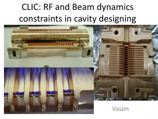
PLACET input: dipole wake function • PETS Impedance simulated and a set of discrete dipole modes are extracted to represent the impedance (I. Syratchev) • Each mode implemented in PLACET (fT, wT, QT, bT) and included in the PETS element (D. Schulte) Slide: I. Syratchev
Input to PETS design During the 12 GHz PETS design, beam dynamics simulations were done in an iterative process with the PETS design to ensure small amplification due to transverse wakes
Origin of wake amplification • Further investigation shows the amplification of the envelope occurs towards the end of the bunch • -> mainly the single bunch wake that drives the amplification Collorary: since single bunch wake is sine-like, shorter bunch-length might reduce wake amplification significantly
Instabilities along the beam • NB: Q-factor larger than the nominal increase multi-bunch wake and might lead to instability along the beam • Here illustrater for Q=Q0 and Q=2Q0 • Deemed unacceptable (even if centroid rc envelope is constrained) • NB: trapped modes*** Q=2Q0 Q=Q0
Conclusion: PETS design • Effect PETS transverse wakes mitigated efficiently for nominal PETS parameters • Stability sensitive to higher Q values
Procedure (the rest of presentation: baseline parameters) • We want to specify lattice element alignment tolerances • We require that no single misalignment should drive our centroid (pencil beam) envelope more than 1 mm, rc < 1 mm (max. of 100 machines)
Quadrupoles • effect • limit of static alignment Update table ***
1-to-1 steering • Using simple 1-to-1 steering (SC) forces the beam centroid through the center of each BPM • We assume a BPM accuracy of 20um (limited mainly by static alignment?) • As result the centroid also passed in the order of *** um from each quad
Results 1-2-1 steering • Even if *** • [plot of distribution over machines]
Dispersion-free steering • 1-to-1 correction does not give an adequate steering due to the large variation of dispersive trajectories • We therefore seek to minimize the dispersive trajectories by applying Dispersion-Free Steering (DFS, [Raubenheim** and Ruth, ***] • Our implementation minimized • We want a difference trajectory with large leverage
DFS: test-beam generation • Advantages with this method • quadrupole strengths are kept constant • main-beam and test-beam can be combined in one pulse • Large energy-leverage
Results: DFS • Start of lattice: DFS not effective, due to the small energy difference of the test-beam, but does not matter since ***
Current jitter • Dispersion-free steering: • Dependence on current, versus bins • Lowest energy particles: XX phase-space revolutions • Highest energy partices: YY phase-space revolutions • DFS technique will be performed in bins, with a max. size depending on the current difference • need to perform DFS technique in bins
Not included in the simulations • Resistive-wall wake • The following estimate • Higher-order wakes • Effect should be limited within r < ½a0 (but probably worth looking further into) • Longitudinal effects and phase jitter • Some work in [D. Schulte] • On-going work • Halo simulations • On-going work by I. Ahmed
Failure modes Selected topics
PETS: effect of inhibition • "Petsonov" • Simulated as R/Q=0, QT=2QT0 (worst-case) • the lack of deceleration leads to higher minimum beam energy and thus less adiabatic undamping and less energy spread • dipole wake kicks increase; for a steered trajectory the change of kicks will in addition spoil the steering • the coherence of the beam energy will increase, and thus also the coherent build up of tranverse wakes
TBL From Model to Reality 1: The Test Beam Line (TBL) The Test Beam Line (TBL) is under construction as part of the CLIC Test Facility 3 (CTF3). TBL will be a first prototype for the CLIC decelerator. The targets are, among others, to investigate beam stability and minimum-loss transport during deceleration with high power extraction efficiency. In addition the TBL will serve as test-bed for Beam-Based Alignment of a decelerated beam, and as a general benchmarking of the simulation codes.