Download
1 / 55
550 likes | 843 Views
Architectural Freedom with Serial Interconnects. Internet Telephony Conference Long Beach, CA October 16 th , 2003. Device. Device. Device. Device. Switched Interconnect. 2000’s. Device. Device. Device. Device. Device. Device. 1990’s. Device. Bridge. Device. Device. Device.

E N D
Architectural FreedomwithSerial Interconnects Internet Telephony Conference Long Beach, CA October 16th, 2003
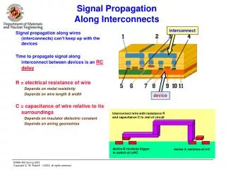
Device Device Device Device Switched Interconnect 2000’s Device Device Device Device Device Device 1990’s Device Bridge Device Device Device Device Device Device Device Device 1980’s Device Device Device Device Interconnect TrendsBus vs. Switched
CPU C P U I O C A R D I O C A R D I O C A R D I O C A R D I O C A R D I O C A R D I O C A R D Memory Framer/ Controller MCH USB Ethernet sATA PCI Bus P-P ICH P-P Typical Bus Based Architecture Single address map Limited to a single processor Difficulty scaling processing requirements with IO needs
Issues with Parallel Buses Parallel Buses Don’t • scale number of connections • scale physically • scale bandwidth • support multiple traffic types • support 5-9’s reliability You only need to reach one limitation to make the move to a new architecture
When to Transition to Switched Interconnect Architectures? ? Interconnect Market Switch Based Designs Bus Based ? Bus Based Designs ? 2000 2010 Make the move when you reach a limitation in current architecture
Benefits of Serial Links • Lower pin count • Smaller connectors • Full bus bandwidth to each node • Full duplex transmissions • Improved reliability • Simpler, less expensive cables • Simpler backplanes • Longer transmission distances
Device Device Device Device Switched Interconnect Device Device Device Device Benefits of Serial Switched Interconnects Performance Scalability: Full Bandwidth to every device High Availability. One device can’t take down entire bus Physical Scalability: Links can span 10’s of meters Single Unified Fabric: Multiple Types and Classes of Traffic Support
Future Architectures Mezzanine level serial switched interconnect • Data moves from processing element to processing element (or to/from I/O elements) as simple memory read/write operations. • Single Unifying Fabric that supports both Processor-to-Processor and Processor-to-Device simultaneously! • Metric becomes“bytes per instruction” not “instructions per byte” • 40+ byte header for Ethernet vs. 8 byte header for AS • HA, QoS, Reliability and Flexibility
Memory Memory Bridge Bridge uC uC Processor uC uC I/O I/O I/O I/O Memory Bridge Bridge Chipset Storage Blades SCSI/FC Cntrl Bridge Bridge Bridge Bridge Bridge Memory DSP DSP GigE MAC Bridge GigE MAC Bridge Result - New Degrees of Architectural Freedom Cache Blades Other IO: Graphics Sensors Image Capture Processor Blades Processor Memory Chipset Storage Blades Storage Blades SCSI/FC Cntrl SF or AS Fabric DSP Blades Bridge Network I/O Blades Memory DSP DSP
StarFabric & Advanced Switching (AS) • StarFabric • Open standard switched interconnect (StarFabric Trade Association) • Based on 622Mb/s SERDES technology • 4X data bandwidth of 2Gb/s • Links can extend beyond single chassis up to 10 meters through standard CAT5 cabling • In production since Spring 2002 • Advanced Switching (AS) • Based on the PCI Express™ architecture • Based on 2.5Gb/s SERDES technology • 4X data bandwidth of 8Gb/s • Available in late 2004 • Scalable, Extensible Serial Switched Interconnects • Lean, High Performance, Low Cost Switching Architectures • Layered Approach Promotes Efficient Modularity
Quality of Service output buffering Class of Service (Virtual Channel) Peer-to-peer Computing Independent address spaces Distributed event handling Path Routing Protection Hardware-based reverse path calculation Hardware-based routing failure notification to source Multicast Routing Table based Fully distributed Multiple talkers and listeners supported Multiple sets of independent resources at endpoints Accessed and protected independently of each other Load/store ordering and bypass support Hardware-based enumeration Credit based flow control S/W accessible capabilities list structures Layered Software model Fabric Primitives Library Bus Drivers Fabric Event Manager Distributed management High Availability End to end CRC Redundant routes Failover Transmission error recovered in hardware Hot plug Robust error detection and notification StarFabric & AS Commonalities
Applications Medical, Sonar, Radar, Communications, Servers, ATEs, Military, etc…all have the same requirement Large amount of data movement Large amount of data processing Large number of processing elements Often multiple processor types DSP, NPU and CPU Wide range of I/O devices Networks Input sensors Imaging and Video devices Displays Storage How does Switch Fabric’s address these Requirements? Embedded Distributed Processing Requirements
Switch Example Fabric - StarFabric Bus Bus Parallel Bus PCI or TDM or Proprietary With one Switch device, connect 6 Bus segments Bridge Bridge StarFabric Frames at 2.5G Transmit and 2.5G Receive Bridge Bridge Bus Switch Bus Redundant fabric interconnect accomplished with a 2nd Switch device Bridge Bridge Bus Bus
CPU 1 Memory Host Bridge SG2010 BRIDGE SG2010 BRIDGE SG2010 BRIDGE CPU 2 CPU 6 Bus 0 Host Bridge Host Bridge Memory Memory . . . Device Device Bus 0 Bus 0 Distributed Processing SG1010 2.5G TX/2.5GRX Up to 40 feet CAT5 Up to 6 processing areas with only one SG1010 6 port Switch
12 Node Fabric Topology Example Inputs to switch match outputs for balanced topology B B S S B B B B B B S S B B B B Switches cascaded together to form larger topologies
B B B B B B B B B B B B B B B B B B B B B B B B B B B B B B S S S S S S S S S S StarFabric Possible Topologies 30 Bus segments connected with 10 Switches, 30 Bridges. Full BW per Bus. 3 links per Switches dedicated to interconnect within the StarFabric
CPU CPU CPU CPU DSP DSP DSP DSP DSP DSP DSP DSP CPU CPU CPU CPU Host Bridge Host Bridge Host Bridge Host Bridge MEM MEM MEM MEM I/O I/O uC uC PCI-to- StarFabric PCI-to- StarFabric PCI-to- StarFabric PCI-to- StarFabric PCI-to- StarFabric PCI-to- StarFabric Storage Blades Storage Blades uC uC PCI-to- StarFabric PCI-to- StarFabric StarFabric IDE, SCSI, or FC 2010 PCI-to- StarFabric PCI-to- StarFabric uC uC GigE MAC GigE MAC Storage Blades IDE, SCSI, or FC PCI-to- StarFabric StarFabric Enabled System CPU Blades DSP Blades • Other I/O • Graphics • Sensors • Image Capture RAM Blades Network I/O Blades Storage Blades
Storage Blades IDE, SCSI, sATA, or FC StarFabric Bridge AS Enabled System Some bridging functionality integrated into switches Processing Blades Storage Blades CPU Storage Blades IDE, SCSI, sATA, or FC CPU Memory Host Bridge Other I/O: - Graphics - Sensors - Image capture StarXpress Bridge Memory Host Bridge StarXpress Bridge uC uC StarFabric Bridge I/O StarXpress Bridge I/O StarXpress Switches DSP Blades Memory Network Blades Memory DSP DSP uC DSP uC DSP StarFabric Bridge GigE MAC StarXpress Bridge GigE MAC StarXpress Bridge
Multi-Layered Protocols Operating System SF/AS Driver P-to-P Driver Peer-Peer Software Legacy PCI Bus Driver (init, enum, config) StarFabric & Advanced Switching Packet Switching Protocol Layer – How data is routed, credit based flow control, event and error handling, etc. Transaction Data Integrity Hardware CRC, 8B10, Link Sync, Auto negotiation, etc. Link status Data Link Point to point, serial, differential,hot-plug, inter-op form factors 622Mb/s per pair for StarFabric 2.5Gb/s per pair for AS Physical
Physical Layer Functions • Electrical signaling • Clocking • Encoding (8B/10B) • Transmission mediums
StarFabric Physical Layer Features 622Mbps differential pair in each direction = 1.25Gbps • Low cost serial physical layer • 622Mbps LVDS • Bi-directional = 1.25Gbps total bandwidth • Four 622Mbps differential pairs aggregated to form one 5Gbps ‘port’ • Hot plug capable point-to-point connections • Chip-to-chip, across backplane and rack-to-rack capable • 13 meter distances with copper used each 5Gbps Four differential pairs in each direction to port create 622Mbps 622Mbps 622Mbps 2.5Gbps 622Mbps 622Mbps 2.5Gbps 622Mbps 5Gbps port 622Mbps 622Mbps
Data Link Layer Functions • Frame formatting • Error coding & recovery (CRC) • Link synchronization
StarFabric Link Layer Frame Formats • Variable-length frames with overhead • Data payloads up to 128 bytes per frame • Efficiency increases with payload size • ~89% for 128 bytes and greater • ~80% for 64 bytes • Link Bandwidth - 128 byte bursts • 622Mbps * 4 diff pairs = • 2.488 Gbps * 0.8 (8B/10B) = • 1.99 Gbps * .89 (overhead) = • 1.77 Gbps * 2 (full-duplex links) = • 3.5Gbps per link Link Overhead 16-byte Line Header 16-byte Line 16-byte Line Link Overhead
AS Protocol AS Packet • Routing Header • Contains Everything Switches Require to Route a Packet • Protocol Specific Header • Modular Sub-Header(s) that Adapt Protocol Variations in Fabric Characteristics • e.g. SAR-ing • Encapsulation of Protocol Payload in it’s Native Format • Clean, High PerformanceTunneling • PI field ID’s Encapsulation Packet Format • LCRC • Switches Check and Regenerate for All Packets Header Routing PI Encapsulated Packet (native format) LCRC
Transaction Layer Functions • Port\Link enumeration • Routing • Flow Control • Error handling • Error notification • Frame arbitration
Routing Methods • Address or Legacy Routing • P2P Base and Limit registers partition a flat global address space • Bridge function translates between PCI transactions and address-routed frames • Unicast Path Routing • Peer to Peer/ Node to Node • Allows Multiple CPUs and I/O to be connected in the same Fabric • Multicast Path Routing • One node to multiple nodes • Frames assigned a multicast group ID at source
Virtual P-P Virtual P-P Virtual P-P Virtual P-P Address RoutingStarFabric & AS Legacy Support Data either flows downstream from host CPU to devices or upstream from devices to host memory Address Space Root complex Limit CPU Base Limit Base Limit Base Device Device Limit Flat global address space with one root complex Device Base
Path Routing StarFabric & AS Multiprocessing Support • High performance, low latency switching • Protocol agnostic • Eliminates upstream/downstream CPU_4 CPU_3 CPU_2 SF or AS Fabric CPU_5 CPU_1 IO IO IO
Fabric Topology Bus 0 Bus 0 Resulting PCI hierarchy root root B B Bus 3 Switches look like pci-to-pci bridges to BIOS/SW Bus 1 Bus 14 S Bus 2 Bus 1 Bus 4 B B S S S Bus 12 Bus 4 Bus 2 B Bus 13 Bus 5 B S S S S S S Bus3 Bus 6 Bus 9 Bus 12 Bus 6 B B B B B B B B Bus 9 B B B B Bus4 Bus 5 Bus7 Bus 8 Bus 10 Bus 11 Bus 13 Bus 14 Bus 10 Bus 11 Bus 7 Bus 8 Links not used in the PCI hierarchy Address Routing and Path Routing • StarFabric Example • Legacy Support – Address Routing, 100% Backwards Compatible • Path Routing – Removes limitation of Legacy and Allows true fabric Clustering
Path Routing Methodology • Unicast Routing • Switches do not require software to manage path routing • Source specifies path to be traveled from origin to destination • Peer-to-Peer communication does not require a central software entity to manage routes • Supports either centralized or fully distributed models • Any Fabric Management capable node can independently compile a graph of the fabric • Multicast Routing • Route header specifies a Multicast Group ID • Group ID indexes a multicast table implemented in switches • Multicast table specifies participating output ports
100 010 … Packet Ingress Packet Egress 100 010 … 010 100 010 … Interpret assigned Turn Pool bits Unicast Path Routing 4 turns Switch #1 4 5 3 6 2 Switch #2 1 7 0 100 7 6 0 Interpret assigned Turn Pool bits 1 5 2 4 3 2 turns • Packet header bit field specifies path through the fabric • Each switch interprets its assigned bits from the “Turn Pool” • Turn Pool Bit field is unique for each path - it is the sender’s “signature”
Packet Ingress Multicast Path Routing Interpret assigned multicast ID (Compare in Multicast Table) OUTPUT PORT 0 1 2 3 4 5 6 7 MGID 0 0 0 1 1 0 0 0 000 001 0 1 0 0 1 1 0 0 010 0 0 0 1 0 1 1 1 4 5 3 6 2 1 7 0 MGID: 010
Path Routing Multiprocessing Domains Destination based memory translation to memory space Address space aperture associated with a path Agent C (unique 64-bit address space) Agent A (unique 64-bit address space) SF or AS Switches Agent B (unique 64-bit address space) Agent D (unique 64-bit address space)
Credit Base Flow Control • Why? … Efficiency! • Guaranteed forward progress thru fabric • Frames only sent if sufficient buffer space is at next node • Frames never require re-transmission unless an error occurs Switch 2, do you have space? Yes I do Switch 1, I have this much space! SG1010 SWITCH 1 SG1010 SWITCH 2 SG2010 BRIDGE PCI BUS Data SG2010 BRIDGE PCI BUS
StarFabric Quality of Service • Separate buffers for traffic classes at each node • Asynchronous and Isochronous Traffic at the same time • Why? … If the async buffer is blocked, isochronous data can still flow! Voice TDM BUS SG3010 BRIDGE SG1010 SWITCH SG1010 SWITCH Isochronous buffer SG1010 SWITCH SG1010 SWITCH PCI BUS SG2010 BRIDGE Data Asynchronous buffer
Software Stack • Software stack provides consistent interface • Applications use IOCTL API into Fabric Bus Driver • Bus driver and embedded applications call directly into FPL User Application Operating System SF or AS Bus Driver Fabric Primitives Library (FPL) Architecture/OS Specific Read/Write Functions Hardware
Fabric Primitives Library Features • Library of routines for fabric enumeration, resource management, and maintenance • Powerful aid to software designers • Provides easy path for developing custom applications • Implemented as multiple objects with well defined interfaces • Source portable to different CPUs • Developers can insert custom software algorithms and policies
Bus Driver Features • Hot link add and removal of entire topology sub branches • OS notified that devices are removed • Discovery process capable of bringing offline components online so device staging not required • Allows for independent power sequencing • Software root selection and migration – Host Failover • Need to focus device ownership to new node • Point events to new node • Write message event handling for multi computing systems • Instead of DoorBells and Scratch pads • Fabric has strong write ordering rules, data is there before the write message
Interconnect Software Concepts • Step 1 – Discovery of the Fabric • What is in the fabric? • How are they connected? • Step 2- Connections in the Fabric • How do I get from here to there? • 3 different types • CSR connections for “status” checks • Bus to Bus connection for sending data • Event connection for error signaling • Step 3 – Events through the Fabric • How do I know if something expected happened? • Ack • How do I know if something unexpected happened? • Link down • Can my computing nodes interrupt other computing nodes? • Multiple CPU Synchronize with each other
Discovery Fabric components scanned by Root Graph initialization FIDs Assigned Done in Hardware for StarFabric Connections Path Specification BARs set up a local memory window to that element Segmented into Blocks Each Block is associated with an Routing Table to establish the header in the packet Destination Address Translation Simple Fabric Root PCI Bus BARs/Setup FID_1 Routing Table 0 Path Table 0 FID_2 2 1 Destination Ch 0 0 FID_4 FID_3 Leaf PCI Bus Leaf PCI Bus
4 Events Signaled events Physical Interrupt pins Chip events Counter overflow, 8B/10B errors Write message events Instead of doorbell and scratch pads, for greater efficiency Fabric events Link up for example Fabric Events EMU buffer that the CPU can read to get all the details vs. having to scan E M U EMU Message Buffer Event Destination Component Event Frame PCI INTx SF or AS Fabric Event Frame INTx Event Source Component Establish were the interrupt goes and what type of information goes with it Event Path Table Chip Event Table Signal Event Table
CPU CPU CPU CPU DSP DSP DSP DSP DSP DSP DSP DSP CPU CPU CPU CPU Host Bridge Host Bridge Host Bridge Host Bridge MEM MEM MEM MEM I/O I/O uC uC PCI-to- StarFabric PCI-to- StarFabric PCI-to- StarFabric PCI-to- StarFabric PCI-to- StarFabric PCI-to- StarFabric Storage Blades Storage Blades uC uC PCI-to- StarFabric PCI-to- StarFabric StarFabric IDE, SCSI, or FC 2010 PCI-to- StarFabric PCI-to- StarFabric uC uC GigE MAC GigE MAC Storage Blades IDE, SCSI, or FC PCI-to- StarFabric Embedded Distributed Processing CPU Blades DSP Blades • Other I/O • Graphics • Sensors • Image Capture RAM Blades Network I/O Blades Storage Blades
Video Server SF or AS Fabric Bridge Bridge Bridge Bridge Bridge Bridge GigE RAID CPU WAN RAID GigE Bandwidth Scalability
Line Card Line Card Line Card Line Card Line Card Line Card Line Card Bridge Bridge Bridge Bridge Bridge Bridge Bridge Host CPU Host CPU Communication Control/Data Plane SF or AS Fabric Bridge Bridge High Availability
DSP DSP DSP DSP DSP DSP Host Bridge Memory Bus 3 Bus 2 SF/AS IP SF/AS IP SF/AS IP . . . IDE to PCI IDE to PCI Bus 0 Graphics Graphics Medical Imaging Centralized computer and image displays DSP farm to process image CPU Host Bridge Memory Bridge I/O from Medical Scanning Device Bridge I/O SF or AS Fabric FPGA Implementation I/O I/O Bridge Storage remote from MR Coils Flexibility
System Disaggregation • Path Routing Allows System Disaggregation • Benefits • Systems become truly disaggregated • Blades become the components • Components can be dynamically assigned and re-assigned • Infrastructure is adaptive • All components can be N+M redundant.
Bridge Bridge Bridge Bridge Bridge Bridge Adaptive Infrastructure Server Blades System 1: System 2: System 3: Processor Processor Storage Blades Processor Memory Storage Blades Memory Chipset SCSI/FC Cntrl Memory Storage Blades Chipset SCSI/FC Cntrl Chipset Storage Blades SCSI/FC Cntrl Bridge Bridge Bridge Network I/O Blades SF or AS Fabric DSP Blades GigE MAC Bridge Memory GigE MAC Bridge Memory DSP Memory DSP GigE MAC Bridge DSP DSP DSP DSP
Initial Design Upgrade Mid Life Kicker S T O R A G E x 2 S T O R A G E x 2 S T O R A G E x 2 S T O R A G E x 2 S T O R A G E S T O R A G E S W I T C H L A N C P U S T O R A G E S T O R A G E S W I T C H S W I T C H L A N C P U C P U S T O R A G E S T O R A G E S T O R A G E S T O R A G E L A N S W I T C H C P U S T O R A G E L A N S T O R A G E S T O R A G E C P U C P U 2 C P U C P U 2 S W I T C H L A N S T O R A G E S T O R A G E S T O R A G E S T O R A G E C P U C P U S T O R A G E S T O R A G E S T O R A G E L A N S W I T C H C P U 2 C P U 2 10 G L A N 10 G L A N Scale capacity Upgrade CPUs & Storage Increase LAN speeds Adaptive InfrastructureLife Cycle Benefits