Download

1 / 12
120 likes | 244 Views
Trellis-based Parallel Stereo Matching. 2007. 4. 9. Media Processor Lab. Sejong univ. E-mail : shelak80@naver.com Dong-seok Kim. Contents. Introduction Stereo Vision Model Center-referenced space Constraints on disparity Estimating optimal disparity Experimental results Conclusion.

E N D
Trellis-based Parallel Stereo Matching 2007. 4. 9. Media Processor Lab. Sejong univ. E-mail : shelak80@naver.com Dong-seok Kim
Contents • Introduction • Stereo Vision Model • Center-referenced space • Constraints on disparity • Estimating optimal disparity • Experimental results • Conclusion
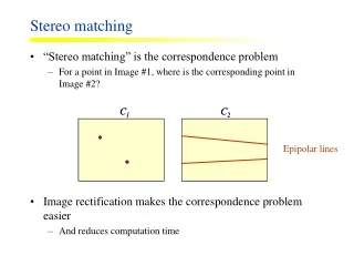
Introduction • Stereo vision is an inverse process that attempts to restore the original scene from a pair of images. • In this paper a new basis for disparity based on center-referenced coordinates is presented that is concise and complete in terms of constraint representation.
Stereo Vision Model (1) • Projection Model • Assumption : coplanar image planes, parallel optical axes, equal focal lengths l, and matching epipolar lines • The inverse match space I is the finite set of points, represented by solid dots, that are reconstructable by matching image pixels. • Left image scan line : fl = [fl1··· flN] • Right image scan line : fr = [fr1··· frN]
Stereo Vision Model (2) • Representation of Correspondence • Each element of each scan line can • have a corresponding element in the other image scan line, denoted (fli,frj) • be occluded in the other image scan line, denoted (fli,Ø) for a left image element (right occlusion) and (Ø, fri) for a right image element (left occlusion) • Left-referenced disparity map : dl = [dl1 ···dlN] • Disparity value : dli ⇔(fli,fri+dli) • Right-referenced disparity map : dr = [dr1 ···drN] • Disparity value : drj ⇔(fli+drj ,frj) .
Center-referenced space (1) • Using only left- or right-referenced disparity, it is difficult to represent common matching constraints with respect to both images. • An alternate center-referenced projection • The focal point pc located at the midpoint between the focal points for the left and right image plane • Plane with 2N + 1 and focal length of 2l • The projection lines intersect with the horizontal iso-disparity lines forms the inverse space D.
Center-referenced space (2) • Center-referenced disparity vector d = [d0··· d2N] • disparity value di indicates the depth index of a real world point along the projection line from site i on the center image plane • If di is a match point : (fl(i – dj + 1)/2 , fr(i + dj + 1)/2) • (fli, frj) is denoted by the disparity di + j – 1 = j – i • The odd function o(x) is used to indicate if di is a match point, that is o(i + di) = 1 when di is a match point.
Center-referenced space (3) • Represent occlusions by assigning the highest possible disparity (Fig. 3) • The correspondence (fl5, fr8) creates a right occlusion for which the real object could lie anywhere in the triangular Right Occlusion Region (ROR) • If only I is used, then the match points (solid dots) in the ROR are used. • D contains additional occlusion points (open dots) in the ROR that are further to the right, which are used instead.
Constraints on disparity • Parallel axes : di≥ 0 • Endpoints : d0 = d2N = 0 • Cohesiveness : di –di – 1 ∈ {–1, 0, 1} • Uniqueness : o(i + di) = 1⇒di–1 = di = di+1
Estimating optimal disparity • DP techniques progressing through the trellis from left to right (site i = 0, …, 2N). In recursive form, the shortest path algorithm for disparity is formally given by: • Initialization : Endpoint has zero disparity • Recursion : At each site i = 1, … 2N, find the best path into each node j. if i+j is even,otherwise • Termination : i = 2N and j = 0. • Reconstruction : Backtrack the decisions. .
Conclusion • We have used a center-referenced projection to represent the discrete inverse space for stereo correspondence. • This space D contains additional occlusion points which we exploit to create a concise representation of correspondence and occlusion. • The algorithm was tested on both real and synthetic image pairs with good results.