Download
1 / 16
160 likes | 294 Views
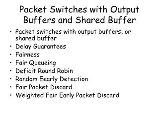
Packet Switches with Output Buffers and Shared Buffer. Packet switches with output buffers, or shared buffer Delay Guarantees Fairness Fair Queueing Deficit Round Robin. Packet Switches with Output Buffers. Packet Switches with Shared Buffer. Delay Guarantees.

E N D
Packet Switches with Output Buffers and Shared Buffer • Packet switches with output buffers, or shared buffer • Delay Guarantees • Fairness • Fair Queueing • Deficit Round Robin
Delay Guarantees • All flows must police their traffic: send certain amount of data within one policing interval • E.g. 10Mbps flow should send 10Kb within 1ms • If output is not overloaded, it is guaranteed that the data passes the switch within one policing interval
Policing Schemes • Simplest TDM scheme is to admit 1 packet each 1/r seconds, where r is the rate. This scheme incurs the large delay for bursty traffic. • Windowing scheme: initially counter is W, flow counter is incremented by 1 W/r seconds after apacket is transmitted, a packet is admitted when counter is positive and then counter is decremented by 1. • Leaky bucket scheme: counter is incremented by 1 every 1/r seconds, and its maximum value is W. Etc. • Many papers calculate the delay that some scheduling algorithm incurs when the traffic is policed by using leaky bucket scheme.
Fairness • When some output is overloaded, its bandwidth should be fairly shared among different flows. • What is fair? • Widely adopted definition is max-min fairness. • The simplest definition (for me) for fair service is bit-by-bit round-robin (BR).
Fairness Definitions • Max-min fairness: • No user receives more than it requests • No other allocation scheme has a higher minimum allocation (received service divided by weight w) • Condition (2) recursively holds when the minimal user is removed • General Processor Sharing: if Si(t1,t2) is the amount of traffic of flow i served in (t1,t2) and flow i is backlogged during , then it holds
Examples • Link bandwidth is 10Mbps; Flow rates: 10Mbps, 30Mbps; Flow weights: 1,1; Fair shares: 5Mbps, 5Mbps • Link bandwidth is 10Mbps; Flow rates: 10Mbps, 30Mbps; Flow weights: 4,1; Fair shares: 8Mbps, 2Mbps • Link bandwidth is 10Mbps; Flow capacities: 4Mbps, 30Mbps; Flow weights: 3,1; Fair shares: 4Mbps, 6Mbps • Homework: Link bandwidth 100Mbps; Flow rates: 5,10,20,50,50,100; Flow weights: 1,4,4,2,7,2; Fair shares ?
Fairness Measure • It is obviously impossible to implement bit-by-bit round-robin • Other practical algorithm will not be perfectly fair, there is a trade-off between the protocol complexity and its level of fairness • Fairness measure is defined as: where flows i an j are backlogged during (t1,t2) and should be as low as possible
Deficit Round Robin • Proposed by Shreedhar and Varghese at Washington University in St. Louis • In DRR, flow i is assigned quantum Qi proportional to its weight wi, and counter ci. Initially counter value is set to 0. The number of bits of packets that are transmitted in some round-robin round must satisfy ti<ci+Qi. And counter is set to new value ci=ci+Qi-ti. If queue gets emptied ci=0; • The complexity of this algorithm is O(1) because a couple of operations should be performed within a packet duration time, if algorithm serves non-empty queue whenever it visits the queue.
Packet Switches with Input Buffers • Switching fabric • Electronic chips (Mindspeed, AMCC, Vitesse) • Space-wavelength selector (NEC, Alcatel) • Fast tunable lasers (Lucent) • Waveguide arrays (Chiaro) • Scheduler • Packets compete not only with the packets destined for the same output but also with the packets sourced by the same input. Scheduling might become a bottleneck in a switch with hundreds of ports and gigabit line bit-rates.
Scheduling Algorithms for Packet Switches with Input FIFO Buffers • Each input sends request for its HOL packet to the corresponding output. Each output grants one input, and this input-output pair will be connected in the next time slot. • Output utilization when inputs are fully loaded is: U=1-(1-1/N)N-1=0.63
3 4 4 4 4 4 4 2 2 1 1 1 1 1 1 2 1 2 1 2 1 2 1 2 1 2 1 2 1 1 1 1 1 4 3 3 3 3 3 4 3 3 3 3 3 2 4 1 2 3 4 4 4 1 1 1 2 1 1 1 .. .. .. .. .. .. .. .. .. .. .. .. .. .. .. .. .. .. .. .. .. .. .. .. .. .. .. .. .. .. .. .. .. .. .. .. .. .. .. .. .. .. .. .. .. .. .. .. .. .. .. .. .. .. .. .. .. .. .. .. Scheduling Algorithms for Packet Switches with Input FIFO Buffers
Scheduling Algorithms for Packet Switches with Input Bufferswith Virtual Output Queues (VOQ) • In parallel iterative matching (PIM), SLIP or dual round-robin (DRR) inputs send requests to outputs, outputs grant inputs, and inputs then grant outputs in one iteration that repeats. • Sequential greedy scheduling (SGS), wavefront arbitering (WFA) are maximal matching algorithm that is simple to implement and guarantee throughput. Maximal matching algorithm does not leave input-output pair unmatched if both input and output are idle.
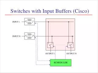
Typical Central Controllers (Cisco) PIM, SLIP (Cisco GSR), DRR