Download
1 / 22
220 likes | 357 Views
Computer Graphics. Chapter 4 2D Viewing Algorithms. Coordinate Systems. y. v. (u,v). (x, y). 0. x. 0. u. Device Coordinates : Device dependent Limits Positive Integer values. World Coordinates : User-Defined Limits Floating point values. Window : A rectangular region

E N D
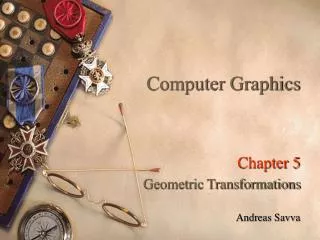
Computer Graphics Chapter 4 2D Viewing Algorithms
Coordinate Systems y v (u,v) (x, y) 0 x 0 u • Device Coordinates: • Device dependent Limits • Positive Integer values • World Coordinates: • User-Defined Limits • Floating point values
Window: A rectangular region in World Coordinate System. Viewport: A rectangular region in Device Coordinate System. (0,300) (0,0) (360,0)
Window to Viewport Transformation We denote the boundaries of the world window by four real values xmin, ymin, xmax, ymax denoting its left, bottom, right, top margins respectively. Similary the boundaries of the viewport on the screen are defined by four integer values umin, vmin, umax, vmax. When a graphics display is generated using arbitrary coordinates on the world window, the important problem encountered in viewing this display on the actual viewport on the screen is to have a function which maps every point (x,y) on the window to a corresponding point (u,v) on the viewport. The following window to viewport transformation achieves this relationship.
Window to Viewport Transformation (xmax, ymax) (x, y) (umax, vmax) (u, v) (xmin,ymin) (umin, vmin) (x, y) (u, v)
Window to Viewport Transformation u = c1x + c2 v = d1y + d2
Window to Viewport Transformation 400 0.2 100 0.1 -0.05 +0.05 250 550 u = 3000 x + 400 v= 3000 y 200
Aspect Ratio • Aspect Ratio = Width/Height. • Aspect ratio of a world window = (xmax-xmin) / (ymax-ymin). • Aspect ratio of the viewport = (umax-umin) / (vmax-vmin). • The transformation from the window to viewport is said to preserve the aspect ratio, if both the above quantities are same. In such a case, we have c1 = d1. When this condition is satisfied, the mapping from the window to the viewport is distortion-free.
Window to Viewport Transformation For distortion-free mapping from the window to the viewport, we must have c1 = d1(in magnitude) 400 0.2 100 0.1 -0.05 +0.05 250 350 u = 1000 x + 300 v= 3000 y 200
Line Clipping • A line is required to be clipped against a rectangular clipping window such that the portion of the line that falls outside the window is not displayed. • There are many possible arrangements of a segment with respect to the window. • We therefore need an organized approach to identify the correct situation and to compute the new end points of each clipped segment. • Efficiency is important because a typical picture contains thousands of line segments, each of which must be clipped against a window.
Line Clipping Clipping Window Window
Cohen-Sutherland Algorithm A rapid divide-and-conquer approach to the line clipping Clipping window Trivial Accept: When both end points are inside the window, and therefore the line is completely visible. Trivial Reject: When both end points are outside the window and on the same side of the window. Then the line is completely outside, and hence can be rejected.
Region Codes A point is assigned a unique region code depending on the location of the point with respect to the window. A B R L 1001 1000 1010 0000 0001 0010 Clipping window 0101 0100 0110
Region Codes Trivial Accept 0000 0000 r1 == 0000 and r2 == 0000 (r1OR r2) == 0000 (OR: Bitwise)
Region Codes Trivial Reject 1010 0010 r1 and r2 have a common bit set to 1 (r1AND r2) 0000 (AND: Bitwise)
Region Codes “Other Cases” 1001 1010 0000 0100
Region Codes “Other Cases” i. The point that lies outside the window is considered. (This is the point whose region code is non-zero). ii. For the above point, an edge outside which the point lies is identified. (If a particular bit is non-zero, the corresponding edge of the window is considered). iii. The intersection of the line with the edge is computed. The initial point in (i) is now replaced by the new intersection point. Its region code is computed. iv. The conditions for the “trivial accept” or “trivial reject” or “other case” is again checked for the new line segment.
Region Codes 1010 0000 Trivial Accept 0000
Computing Intersection Point (Eg.) The equation of the line PQ is The intersection point A lies on the left edge and therefore its x-coordinate is x = xmin. To get the y-coordinate of A, we substitute for x in the above equation of PQ: y = Q A P x=xmin
Computing Intersection Point (Eg.) Now P is replaced by the point A (effectively discarding the segment PA), and the whole process of checking is repeated for the segment AQ. Now both A, Q will have region codes 0000, and hence will satisfy the condition “trivial accept”. Q A P x=xmin