Download
1 / 49
490 likes | 500 Views
Database Design: Object-Oriented Modeling. University of California, Berkeley School of Information Management and Systems SIMS 202: Information Organization and Retrieval. Lecture Outline. Review ER Diagrams Developing the Conceptual Model Assignment 1 Discussion

E N D
Database Design: Object-Oriented Modeling University of California, Berkeley School of Information Management and Systems SIMS 202: Information Organization and Retrieval
Lecture Outline • Review • ER Diagrams • Developing the Conceptual Model • Assignment 1 Discussion • Database Design cont. Object-Oriented Modeling • Logical Design for the Diveshop database
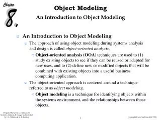
Developing a Conceptual Model • Overall view of the database that integrates all the needed information discovered during the requirements analysis. • Elements of the Conceptual Model are represented by diagrams, Entity-Relationship or ER Diagrams, that show the meanings and relationships of those elements independent of any particular database systems or implementation details. • Can also be represented using other modeling tools (such as UML)
Customer Dive Order Line item Shipping information Dive Equipment/ Stock/Inventory Dive Locations Dive Sites Sea Life Shipwrecks Entities
Ordering: Full ER Customer No DiveCust 1 Destination Name ShipVia Customer No Destination no n ShipVia ShipVia 1 n DiveOrds n Dest 1 1 Destination Order No Order No n DiveItem Item No n 1 DiveStok Item No
Destination/ Sites Destination Name Customer No Destination no 1 n DiveOrds Dest 1 Destination no Destination Order No Site No n Sites
Sites and Sea Life 2 Site No Destination no Sites 1 n Site No BioSite Species No n 1 BioLife Species No
Sites and Shipwrecks Site No Destination no Sites 1 1/n ShipWrck Site No
DiveShop ER Diagram Customer No DiveCust Destination Name ShipVia Customer No Destination no ShipVia ShipVia DiveOrds Dest Destination no Destination Order No Site No Order No Sites DiveItem Site No BioSite ShipWrck Item No Species No Site No DiveStok BioLife Item No Species No 1 n n 1 n 1 1 1 n n 1 1 n 1/n n n 1 1
What is Missing?? • Not really an “enterprise-wide” database • No personnel • Sales people • Dive masters • Boat captains and crew • payroll • Local arrangements • Dive Boats • Hotels • Suppliers/Wholesalers for dive equipment • Orders for new/replacement equipment • No history (only current or last order)
Assignment 1 Discussion • Problems?
Lecture Outline • Review • ER Diagrams • Developing the Conceptual Model • Assignment 1 Discussion • Database Design cont. Object-Oriented Modeling • Logical Design for the Diveshop database
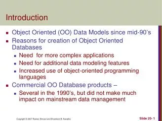
Object-Oriented Modeling • Becoming increasingly important as • Object-Oriented and Object-Relational DBMS continue to proliferate • Databases become more complex and have more complex relationships than are easily captured in ER or EER diagrams • (Most UML examples based on McFadden, “Modern Database Management”, 5th edition)
Object Benefits • Encapsulate both data and behavior • Object-oriented modeling methods can be used for both database design and process design • Real-World applications have more than just the data in the database they also involve the processes, calculations, etc performed on that data to get real tasks done • OOM can be used for more challenging and complex problems
Unified Modeling Language (UML) • Combined three competing methods • Can be used for graphically depicting • Software designs and interaction • Database • Processes
CLASS • A class is a named description of a set of objects that share the same attributes, operations, relationships, and semantics. • An object is an instance of a class that encapsulates state and behavior. • These objects can represent real-world things or conceptual things. • An attribute is a named property of a class that describes a range of values that instances of that class might hold. • An operation is a named specification of a service that can be requested from any of a class's objects to affect behavior in some way or to return a value without affecting behavior
UML Relationships • An relationship is a connection between or among model elements. • The UML defines four basic kinds of relationships: • Association • Dependency • Generalization • Realization
UML Diagrams • The UML defines nine types of diagrams: • activity diagram • class diagram • Describes the data and some behavioral (operations) of a system • collaboration diagram • component diagram • deployment diagram • object diagram • sequence diagram • statechart diagram • use case diagram
Class Diagrams • A class diagram is a diagram that shows a set of classes, interfaces, and/or collaborations and the relationships among these elements.
UML Class Diagram DIVEORDS Order No Customer No Sale Date Shipvia PaymentMethod CCNumber No of People Depart Date Return Date Destination Vacation Cost CalcTotalInvoice() CalcEquipment() Class Name List of Attributes List of operations
Object Diagrams 307:DIVORDS Order No = 307 Customer No = 1480 Sale Date = 9/1/99 Ship Via = UPS PaymentMethod = Visa CCNumber = 12345 678 90 CCExpDate = 1/1/01 No of People = 2 Depart Date = 11/8/00 Return Date = 11/15/00 Destination = Fiji Vacation Cost = 10000
Differences from Entities in ER • Entities can be represented by Class diagrams • But Classes of objects also have additional operations associated with them
Operations • Three basic types for database • Constructor • Query • Update
Associations • An association is a relationship that describes a set of links between or among objects. • An association can have a name that describes the nature of this relationship. You can put a triangle next to this name to indicate the direction in which the name should be read.
Associations • An association contains an ordered list of association ends. • An association with exactly two association ends is called a binary association • An association with more than two ends is called an n-ary association.
Associations: Unary relationships 0..1 * Person Employee Is-married-to manages 0..1 0..1 manager
Associations: Binary Relationship Employee Product Line Student Parking Place Course Product * 1 0..1 Registers-for Is-assigned contains * 0..1 * One-to-one Many-to-many One-to-many
Associations: Ternary Relationships Part * Vendor Supplies Warehouse * *
Association Classes Student Course Registers-for * * Registration ________________ Term Grade ________________ CheckEligibility() Computer Account _________________ acctID Password ServerSpace issues * 0..1
Derived Attributes, Associations, and Roles Student _________ name ssn dateOfBirth /age Course Offering ____________ term section time location Course ____________ crseCode crseTitle creditHrs Scheduled-for Registers-for * * * 1 Derived attribute * * Derived role /participant {age = currentDate – dateOfBirth} /Takes Derived association
Generalization Employee ____________ empName empNumber address dateHired ____________ printLabel() Consultant _______________ contractNumber billingRate _______________ computeFees() Salaried Employee _______________ Annual Sal stockoption _______________ Contributepension() Hourly Employee _______________ HourlyRate _______________ computeWages()
Other Diagramming methods • SOM (Semantic Object Model) • Object Definition Language (ODL) • Not really diagramming • Access relationships display • Hybrids
Application of SOM to Diveshop DIVECUST Name 1.1 Address Street City StateProvince ZIPPostalCode Country Phone FirstContact 1.1 1.1 1.1 1.1 1.1 1.1 1.1 1.1 DIVEORDS 1.N
DIVEORDS DIVEORDS id OrderNo SaleDate DIVECUST SHIPVIA DESTINATION DIVEITEM PaymentMethod CCNumber CCExpDate NoOfPeople DepartDate ReturnDate VacationCost
DiveShop ER Diagram Customer No DiveCust Destination Name ShipVia Customer No Destination no ShipVia ShipVia DiveOrds Dest Destination no Destination Order No Site No Order No Sites DiveItem Site No BioSite ShipWrck Item No Species No Site No DiveStok BioLife Item No Species No 1 n n 1 n 1 1 1 n n 1 1 n 1/n n n 1 1
Customer Dive Order Line item Shipping information Dive Equipment Stock/Inventory Dive Locations Dive Sites Sea Life Shipwrecks Entities
Logical Design: Mapping to a Relational Model • Each entity in the ER Diagram becomes a relation. • A properly normalized ER diagram will indicate where intersection relations for many-to-many mappings are needed. • Relationships are indicated by common columns (or domains) in tables that are related. • We will examine the tables for the Diveshop derived from the ER diagram
Assignment 2: Due Oct. 1 • The following information should be turned in for the preliminary design of your personal database project. • A general description of the data you will be using for the database, and what uses you might expect the database to have. • A preliminary data dictionary for the entities and attributes and format of the data elements of the database. You should have at least 5 entities with some logical connections between them. The data dictionary consists of all of the attributes that you have identified for each entity, along with indication of whether the attribute is a primary key (or part of a primary key), and what format the data will be (e.g.: text, decimal number, integer, etc.) • Produce an entity-relationship diagram of the database OR a UML diagram. • These will be preliminary design specifications, so do not feel that you must follow everything that you describe here in the final database design.
Next Time • Normalization • Normal Forms • For next 2 weeks: Guest speakers • Sep 17: Marti Hearst on Flamenco. • Sep 24: Mark Butler, Interwoven • Sep 26: Avi Rappoport, Search.com