Download
1 / 13
130 likes | 138 Views
Mechanics of Materials Engr 350 - Lecture 24 Beam Equilibrium and VM Diagrams. What is a beam?. Structural member that supports a load long relative to cross-sectional dimensions straight prismatic support internal shear forces and bending moments. Types of supports. Pinned Connection.

E N D
Mechanics of Materials Engr 350 - Lecture 24Beam Equilibrium and VM Diagrams
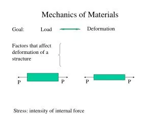
What is a beam? • Structural member that supports a load • long relative to cross-sectional dimensions • straight • prismatic • support internal shear forces and bending moments
Types of supports Pinned Connection Fixed Support Roller Support
Beam Conditions Simply Supported Cantilever Simply Supported with Overhang What do the reactions at each end look like for each of these?
Types of loadings • Concentrated loads and concentrated moments don’t really exist. But many times they are a good approximation. • CW concentrated moment causes upward jump on diagram
Shear and moment in beams • Before we can determine internal stresses in beams, we must know the internal shear (V) and moment (M) • This is accomplished by “cutting” the beam and analyzing it via equilibrium methods. ie. method of sections
Sign Conventions for Shear and Moment • Positive shear • Makes shear element want to rotate clockwise • Positive moment • Makes beam want to ‘smile’
Rules for Creating VM Diagrams Shear diagram • Concentrated forces cause a jump in the shear diagram at the location of the force • Change in shear force between any two locations is equal to the area under the distributed load diagram • Slope of any shear diagram at any location is equal to the distributed load value at that location Moment diagram • Change in moment between any two locations is equal to the area under the shear diagram • Slope of the moment diagram at any location is equal to the shear force at that location • Concentrated moments cause a jump in the internal bending moment at the point of application. CW external moment causes a positive jump
Graphical Method for VM Diagrams • The direct method can become cumbersome when many loads are applied to a beam. • We want to develop a method for creating shear and moment diagrams more quickly • Consider a beam with general loads • Take a section of this beam
General procedure for graphical construction • Complete the load diagram or FBD • Follow the “rules” to conduct the shear diagram • Locate key points on shear diagram • Follow the “rules” to construct the moment diagram
Example - draw the shear force and bending moment diagram for the beam below • V • M
Second Example - draw the shear force and bending moment diagram for the beam below • V • M