Download

1 / 52
750 likes | 1.74k Views
Sumo Robot. From Ground Zero to Competition. Robot Chronology . From the first use of the word “robot” in a Czechoslovakian novel to characters in Star Wars, people have been fascinated with mechanical beings. More fascinating is the real world of robots.

E N D
Sumo Robot From Ground Zero to Competition
Robot Chronology From the first use of the word “robot” in a Czechoslovakian novel to characters in Star Wars, people have been fascinated with mechanical beings. More fascinating is the real world of robots.
1954 George Devol designs the first programmable robot and coins the term “Universal Automation,” planting the seed for the name of his future company, Unimation. 1960 Unimation is purchased by Condec Corporation, and development of Unimate Robot Systems begins. American Machine and Foundry, later known as AMF Corporation, markets the first cylindrical robot, called the Versatran, designed by Harry Johnson and Veljko Milenkovic. 1962 General Motors purchases the first industrial robot from Unimation and installs it on a production line. This manipulator is the first of many Unimates to be deployed. 1967 Japan imports the Versatran robot from AMF. The Versatran was the first robot imported into Japan. 1968 Kawasaki licenses hydraulic robot design from Unimation and starts production in Japan. 1968 SRI builds Shakey, a mobile robot with vision capability, controlled by a computer the size of a room.
1970 Professor Victor Scheinman of Stanford University designs the Standard Arm. Today, its kinematic configuration remains known as the Standard Arm. 1973 Cincinnati Milacron releases the T3, the first commercially available mini-computer-controlled industrial robot (designed by Richard Hohn). 1976 Robot arms are used on Viking 1 and 2 space probes.Vicarm Inc. incorporates a microcomputer into the Vicarm design. 1978 Using technology from Vicarm, Unimation develops the PUMA (Programmable Universal Machine for Assembly). The PUMA can still be found in many research labs today. 1979 Sankyo and IBM market the SCARA (selective compliant articulated robot arm) developed at Yamanashi University in Japan. 1982 Fanuc of Japan and General Motors form joint venture in GM Fanuc to market robots in North America.
1986 With Unimation license terminated, Kawasaki develops and produces its own line of electric robots. 1994 CMU Robotics Institute's Dante II, a six-legged walking robot, explores the Mt. Spurr volcano in Alaska to sample volcanic gases. 1997 NASA's Mars PathFinder mission captures the eyes and imagination of the world as PathFinder lands on Mars, and the Sojourner Rover robot sends back images of its travels on the distant planet. 1997 Honda showcases the P3, the 8th prototype in a humanoid design project started in 1986. 2000 Honda showcases Asimo, the next generation of its series of humanoid robots. 2001 Sony releases the second generation of its Aibo robot dog.
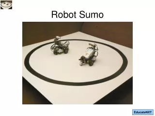
Fujisoft Chairman Hiroshi Nozawa invented the Robot Sumo competitions to get high-school students interested in robotics. Held in August 1989, the first exposition game featured 33 robots; 147 participated. Robot Sumo the Beginning
Sumo Robot Contest • Simple Rules • Low Startup Cost • Simple Programming • Lots of Fun!
Object of contest is to push the opponent out of the ring. On edge of ring is not a loss. On side is still not a loss. Even upside down is not a loss. Only touching outside of ring loses.
The Playing Field (Dohyo) Although official Japanese rules call for an aluminum disk covered with vinyl, most local competitions are played on a wooden disk covered with paint or countertop materials.
Definition of Match A match is between two robots. The robots are constructed and programmed by an individual or a team. However, only one person is allowed at ringside when the match begins. At the beginning of the match, the human contestants are to bow to each other and place the robots on the Dohyo (ring) according to the instructions of the referee. Bad conduct and disrespect by either contestant can have them disqualified and the match given to the opponent. When the referee says “Start,” the contestants power on the robots, and then move two meters away from the Dohyo. Five seconds later, the robots start to move. A false start (moving before five seconds or not moving at all) will cause a restart. Only one restart per match is allowed. A second false start will result in a forfeit of the match and a Yuko (point) given to the opponent. The match continues for three minutes or until a Yuko is scored. If at the end of three minutes both robots are still in the ring, the referee will award the Yuko to the best performing robot. If the referee cannot determine a decisive winner he can call for a rematch. The contest continues until one robot wins two out of three matches. At the end of each match, the human contestants bow to each other. Here again bad conduct or disrespect can forfeit the match even if a Yuko has already been awarded.
Mini Sumo Robot Specifications • Must be fully autonomous. • Must be less than 10cm wide by 10cm long. Height is not restricted, and the robot can change dimensions after start of a match. • Must weigh less than 500g. • Cannot have sticky tires or suction devices.
Starter Kits OWI Kit $60 LEGO MindStorm $200 Solarbotics $90 - $150 MARK III $100 Paralax $130
MARK III Robot Features • Not just for mini-sumo, but for general-purpose robotics. • Modular and adaptable with great potential for expansion. • Computer Interface - Standard serial RS232. DB9 connector. 8N1, no handshaking. • "Open source" hardware, so others can use the design. • 40-pin OOPic-compatible header for interfacing to mezzanine boards and/or OOPic-compatible expansion boards. All PIC lines brought out to header. • Low-battery indicator.
Start with the bare PCB Notice that some of the reference designators are hidden when parts, such as R12 and R13, are installed.
Assembly is done in steps, from the shortest components to the tallest ones. This is so the board can be assembled upside down for soldering. If you are going to add connectors to U5 and U7, make C10 and C12 leads longer because the backside of the connector extends past the cap.
Care must be taken when installing the resistors. It can be difficult to read the color code, and the tolerance band only confuses matters. To confuse things more, extra resistors are shipped. A good way to start is to lay out the resistors by value in separate piles. If you have an ohmmeter, you can use it to verify any values that you have questions about.
The ICs are simple. There are only two that are not in sockets, and they are not the same size. Just make sure the notch or dot on the IC matches the mark on the PCB,
The electrolytic capacitors, as well as the diode, are polarized devices, which means that they must be inserted in a particular direction. The capacitors have the negative leg marked, and the circuit board has the positive marked. So, logic dictates that the mark on the capacitor must face opposite of the mark on the board. Add switch here. The diode goes here with the stripe matching the line at the arrow on the board.
The LEDs are inserted so that the short lead goes into the square pad. The square pad is shaded white on the silkscreen. Add the resonator Y1.
Adding the sockets and large switch takes a little more forethought because they are not all the same height. As has been the practice up to this point, solder in the shorter parts first. Take care to get the polarity correct. The picture does not show the U4 socket populated. For the OOPIC version there should be a socket here.
Now insert the ICs. Notice again the socket at U4 is not shown. Also, JP1 needs jumpers from 3 to 5 and 4 to 6. The circuit board is now complete.
Start Chassis Assembly Connect the standoffs to the chassis. The holes in the standoffs should be closest to the chassis. Notice that the pictured chassis is not like the actual chassis. The front lip points up, not down as pictured.
Although the instructions tell you to add the servo motors here, and it is easier to, resist the temptation, as you will need to zero out the servos later, when you’re programming the robot.
Although the Sumo robot needs only two line sensors to detect the white line, the circuit structure requires all three to be installed.
The batteries for the servo motors are held on with velcro strips. It is easiest to press the velcro strips together, tape them to the battery pack, and then stick the velcroed battery pack to the chassis. If you have more than one battery pack, you will need to decide on a standard orientation for the hook and wool sides of the velcro on the battery packs and the robot chassis. That way changing battery packs will not be foiled by having the velcros on the battery pack mismatched to the velcros on the chassis.
With the PCB on the robot, you are nearly ready to start programming.
This picture shows the 9V battery but not how it is connected to the PCB. Notice how the metal case of the battery is just below the PCB. It would be a very good idea to insulate the battery case with paper or tape to prevent it from shorting out the PCB during the competition.
Programming the Robot • Getting and loading software • Connecting the computer to the robot • Creating virtual circuits • Testing virtual circuits • Testing sensors and servo motors • And finally, writing Sumo code!
Line Sensor • Digital Test • Analog Test
If feedback from line sensor is below 23 (30 – fuzziness), make output equal to one. If feedback from line sensor is above 37, make output equal to zero. If feedback is in between 23 and 37, make no change from the last state.
Const SensorLineLeft = 7; oCompare2 oSensorLineLeftCompare = new oCompare2; oSensorLineLeftCompare.Input.Link(oSensorLineLeft.Value); oA2D oSensorLineLeft = new oA2D; oSensorLineLeft.IOline = SensorLineLeft; oSensorLineLeft.Operate = cvTrue; Const SensorLineWhiteLevel = 30; // Link oSensorLineCompareByte to reference input 1 & 2 oSensorLineLeftcompare.ReferenceIn1.Link(oSensorLineCompareByte); oSensorLineLeftcompare.ReferenceIn2.Link(oSensorLineCompareByte); oSensorLineLeftCompare.Operate = cvTrue; Const SensorLineBandgap = 7; oSensorLineLeftCompare.Fuzziness = SensorLineBandgap; oSensorLineLeftWire.Input.Link(oSensorLineLeftCompare.Below); oSensorLineLeftWire.Output.Link(oSensorLineLeftBit); oSensorLineLeftWire.Operate = cvTrue;