Download
1 / 15
170 likes | 331 Views
Two Phase “Bubbly” Fluid Flow in a Vertical Chamber A Finite Element Analysis (FEA) Numerical Model. Craig E. Nelson - Consultant Engineer. Purpose of the Computational Fluid Dynamic Experiment :

E N D
Two Phase “Bubbly” Fluid Flow in a Vertical Chamber A Finite Element Analysis (FEA) Numerical Model Craig E. Nelson - Consultant Engineer
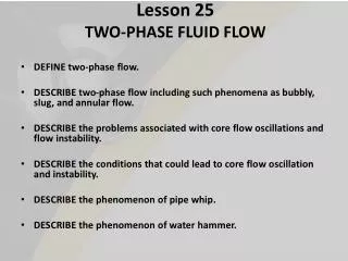
Purpose of the Computational Fluid Dynamic Experiment: • Learn how gas-liquid “bubbly flow” patterns evolve and change as a function of a porous membrane outlet gas fraction • Develop a sense for how gas-liquid velocity varies as a function of gas fraction • Develop understanding of how intra-channel pressure varies as a function of gas fraction
Model Assumptions for Computational Fluid Dynamic Experiment: • The Liquid is Water • Channel dimensions are large enough that surface tension may be neglected. • The gas exists in the form a of nebulous cloud of small, particle like bubbles that convect and diffuse into the surrounding water much like smoke particles would. • Bubbly liquid “sticks” to the channel walls in the same manner as all normal fluids would when channel dimensions are not of nano scale
Channel Outlet (0 Pa Pressure) Flow Barrier “Bubbly” Fluid Passing Out from a Membrane “Window” (Vx = 1 mm/sec) 10 mm 5 mm Small Recirculation “Eddy Current” Inlet “Window” 2 mm Model Geometry and General Flow Description
0 % Gas Vmax = 3.0 mm/sec 10 % Gas Vmax = 4.0 mm/sec 20 % Gas Vmax = 4.2 mm/sec 30 % Gas Vmax = 6.6 mm/sec 40 % Gas Vmax = 9.5 mm/sec Flow Velocity Vector Magnitude for Several “Bubbly” Fluid Gas-Liquid mixture Concentrations
0 % Gas 10 % Gas 20 % Gas 30 % Gas 40 % Gas Vertical Flow Velocity Amplitude for Several “Bubbly” Fluid Gas-Liquid mixture Concentrations
0 % Gas 10 % Gas 20 % Gas 30 % Gas 40 % Gas Horizontal Flow Velocity Amplitude for Several “Bubbly” Fluid Gas-Liquid mixture Concentrations
0 % Gas 10 % Gas 20 % Gas 30 % Gas 40 % Gas Flow Velocity Vectors for Several “Bubbly” Fluid Gas-Liquid mixture Concentrations Notice How the Small Initial Eddy Current Grows as the Gas Fraction Increases
0 % Gas 10 % Gas 20 % Gas 30 % Gas 40 % Gas Gas Fraction for Several “Bubbly” Fluid Gas-Liquid mixture Concentrations
0 % Gas 10 % Gas 20 % Gas 30 % Gas 40 % Gas Fluid Mixture Density for Several “Bubbly” Fluid Gas-Liquid mixture Concentrations
0 % Gas Fraction 40 % Gas Fraction Fluid Mixture Channel Outlet Velocity Profiles for 0 % and 40% Gas Fraction Notice that the 40% Gas Fraction Mixture Exhibits Reverse Flow Over Part of the Channel Outlet
0 % Gas Fraction 40 % Gas Fraction Fluid Mixture Longitudinal “Cut” Density Profile for 0 % and 40% Gas Fraction
0 % Gas Fraction 40 % Gas Fraction Fluid Mixture Longitudinal “Cut” Pressure Profile for 0 % and 40% Gas Fraction Notice that the 40% Gas Fraction Mixture Exhibits Negative Pressure at the Channel Bottom End Relative to the Upper Channel Outlet while the 0% case Exhibits Positive Pressure in the Same Region
0 % Gas Fraction 40 % Gas Fraction Fluid Mixture Longitudinal “Cut” Gas Fraction Profile for 0 % and 40% Gas Fraction
Summary of Results for Computational Experiment: • As gas fraction increases, the “bubbly” fluid flow pattern gradually changes from “straight up and out” to “up and out with relatively strong “recirculation”. • As gas fraction increases, maximum “bubbly” fluid flow velocity increases and the location of the velocity maximum moves closer to the porous window outlet surface and “lower down” in the outlet channel. • As cell power increases, the pressure at the bottom of the outlet channel becomes progressively more negative – Out flowing Bubbly fluid apparently “pulls a vacuum” on the lower outlet channel region • Additional Comments: • Almost no gas bubbles ever reach the “bottom” of the outlet flow Channel • As gas fraction increases, the change in fluid density at the top end of the outlet channel is rather dramatic – Under these circumstances, aggravating bubble coalescence may be expected • The change in fluid volume flow rate as gas fraction increases is large due to the “expansion” of the overall fluid volume. A negative relative pressure at the channel outlet would be a good idea for effective removal of a high gas fraction fluid mixtures.