Download
1 / 21
210 likes | 363 Views
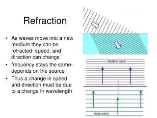
Wavepath Refraction Migration on Near-Surface Refraction Data. Jianming Sheng. Outline. Motivation. Numerical Examples. Wavepath Refraction Migration. Summary. Motivation. Produce better seismic image by Traveltime Tomography + Refraction Migration.

E N D
Wavepath Refraction Migration on Near-Surface Refraction Data Jianming Sheng
Outline • Motivation • Numerical Examples • Wavepath Refraction Migration • Summary
Motivation • Produce better seismic image by Traveltime Tomography + Refraction Migration • Help to reduce the uncertainties in the tomograms.
Outline • Motivation • Numerical Examples • Wavepath Refraction Migration • Summary
G S Imaging Condition T=TSX+TXY+TYG X Y Refraction Migration
Outline • Motivation • Numerical Examples • Refraction Migration • Summary
Numerical Examples • 2D refraction data from INCO • 2D marine data from WesternGeco and ChevronTexaco
2D INCO Refraction Data Courtesy of Alan King Shot spacing: 50 m Shots: 105 Channel: 24 Receiver: 10 m Length: 2.56 sec. Sample: 0.625 ms 2025 traveltimes were picked by Prof. Schuster
CSG #3 Residual vs. Iterations 0 55 Traveltime (sec.) Traveltime (msec.) 0.26 0 220 Offset (m) 5 0 Iterations 40
Traveltime Tomogram 3500 0 2500 Depth (m) 1500 500 150 (m/s) 0 Distance (m) 2000
Ray Density 200 0 140 Depth (m) 80 20 150 (m/s) 0 Distance (m) 2000
Refraction Migration 5 0 Depth (m) 0 150 -5 0 Distance (m) 2000
Tomogram/Refraction Migration 3500 0 2500 Depth (m) 1500 500 150 (m/s) 0 Distance (m) 2000
Numerical Examples • 2D refraction data from INCO • 2D marine data from WesternGeco and ChevronTexaco
Gulf of Mexico seismic line Courtesy of Alan Leeds Shot spacing: 25 m Shots: 990 Channel: 180 Receiver: 25 m Sample: 4 ms Length: 8 sec. A total of 86,736 traveltimes were picked and inverted.
Traveltime Velocity Tomogram 0 2100 1900 Depth (m) 1700 1500 1000 (m/s) 5500 CDP NUMBER 6500
0.60 2700 0.40 0.20 2000 0.00 -0.20 1300 -0.40 -0.60 600 -0.80 -1.00 Ray Density/Refraction Migration 0 Depth (m) 1000 5500 CDP NUMBER 6500
Reflection migration 0 Depth (m) 1000 5500 CDP NUMBER 6500
Outline • Motivation • Numerical Examples • Wavepath Refraction Migration • Summary
Summary • Wavepath refraction migration method • was applied to two field data sets. • Refraction migration can help • reducing uncertainties in tomograms.
Acknowledgment I thank the sponsors of the 2002 UTAM Consortium for their financial support . I thank Alan King and Alan Leeds for providing the data set and helpful instructions. I thank Prof. Schuster for picking the traveltimes.