Download
1 / 51
510 likes | 635 Views
Lec 13: Machines (except heat exchangers). For next time: Read: § 5-4 HW7 due Oct. 15, 2003 Outline: Diffusers and nozzles Turbines Pumps and compressors Important points: Know the standard assumptions that go with each device

E N D
For next time: • Read: § 5-4 • HW7 due Oct. 15, 2003 • Outline: • Diffusers and nozzles • Turbines • Pumps and compressors • Important points: • Know the standard assumptions that go with each device • Know how to simplify the governing equations using these assumptions • Consider what each device would be used for in real-world applications
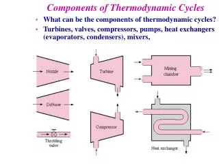
Applications to some steady state systems • Start simple • nozzles • diffusers • valves • Include systems with power in/out • turbines • compressors/pumps • Finish with multiple inlet/outlet devices • heat exchangers • mixers
We will need everything we have covered • Conservation of mass • Conservation of energy • Property relationships • Ideal gas equation of state • Property tables • Systematic analysis approach
Nozzles and Diffusers • Nozzle--a device which accelerates a fluid as the pressure is decreased. V2, p2 V1, p1 This configuration is for subsonic flow.
Nozzles and Diffusers • Diffuser--a device which decelerates a fluid and increases the pressure. V2, p2 V1, p1
For supersonic flow, the shape of the nozzle is reversed. Nozzles
Common assumptions for nozzles and diffusers • Steady state, steady flow. • Nozzles and diffusers do no work and use no work. • Potential energy changes are usually small. • Sometimes adiabatic.
TEAMPLAY • For nozzles, diffusers and other machines--just how important is PE? • The energy in the head of a kitchen match is reportedly about 1 Btu. • How far does 1 lbm have to fall in a standard earth gravity field to “match” this much energy? • Example 5-12 on p. 175 has an enthalpy change h1 - h2 less than 20 Btu. What does your result mean physically for a nozzle or diffuser?
We start our analysis of diffusers and nozzles with the conservation of mass If we have steady state, steady flow, then: And
We continue with conservation of energy We can simplify by dividing by mass flow: 0 0 0 Applying the definition that w=0 and using some other assumptions...
We can rearrange to get a much simpler expression: With a nozzle or diffuser, we are converting flow energy and internal energy, represented by Dh into kinetic energy, or vice-versa.
Sample Problem:Assumptions • SSSF (Steady state, steady flow) - no time dependent terms • adiabatic • no work • potential energy change is zero • air is ideal gas
Sample problem:diagram and basic information OUTLET P2=167 kPa V2=35 m/s INLET T1=300C P1=100 kPa V1=250 m/s m = 7 kg/s
Sample Problem: apply basic equations Conservation of Mass Solve for A2
How do we get specific volumes? Remember ideal gas equation of state? or and We know T1 and P1, so v1 is simple. We know P2, but what about T2? NEED ENERGY EQUATION!!!!
Sample problem - con’t Energy V1 and V2 are given. We need h2 to get T2 and v2. If we assumed constant specific heats, we could get T2 directly
Sample problem - con’t However, use variable specific heats...get h1 from air tables at T1 = 300+273 = 573 K. From energy equation: This corresponds to an exit temperature of 602.2 K.
TEAMPLAY Work problem 5-65
Throttles (throttling devices) • A major purpose of a throttling device is to restrict flow or cause a pressure drop. • A major category of throttling devices is valves.
Typical assumptions for throttling devices • Do no work, have no work done on them • Potential energy changes are zero • Kinetic energy changes are usually small • Heat transfer is usually small
Look at energy equation: Apply assumptions from previous page: 0 0 0 0 We obtain: or
Look at implications: If fluid is an ideal gas: cp is always a positive number, thus:
Discussion Question Does the fluid temperature increase, decrease, or remain constant as an ideal gas goes through an adiabatic valve?
TEAMPLAY Refrigerant 134a enters a valve as a saturated liquid at 200 psia and leaves at 50 psia. What is the quality of the refrigerant at the exit of the valve?
Turbine • A turbine is device in which work is produced by a gas passing over and through a set of blades fixed to a shaft which is free to rotate.
Turbines We’ll assume steady state, Sometimes neglected Almost always neglected
Turbines • We will draw turbines like this: inlet w maybe q outlet
Compressors, pumps, and fans • Machines developed to make life easier, decrease world anxiety, and provide challenging problems for engineering students. • Machines which do work on a fluid to raise its pressure, potential, or speed. • Mathematical analysis proceeds the same as for turbines, although the signs may differ.
Primary differences • Compressor - used to raise the pressure of a compressible fluid • Pump - used to raise pressure or potential of an incompressible fluid • Fan - primary purpose is to move large amounts of gas, but usually has a small pressure increase
Compressors, pumps, and fans Side view End view Centrifugal pump Axial flow Compressor
Sample Problem Air initially at 15 psia and 60°F is compressed to 75 psia and 400°F. The power input to the air is 5 hp and a heat loss of 4 Btu/lb occurs during the process. Determine the mass flow in lbm/min.
Assumptions • Steady state steady flow (SSSF) • Neglect potential energy changes • Neglect kinetic energy changes • Air is ideal gas
What do we know? INLET T1 = 60F P1 = 15 psia OUTLET T2 = 400F P2 = 75 psia
Apply First Law: 0 0 0 0 Simplify and rearrange:
Continuing with the solution.. Get h1 and h2 from air tables Follow through with solution
TEAMPLAY Work problem 5-73E
TEAMPLAY • Use EES and vary the exit pressure from 5 psia to 0.5 psia in increments of 1.0 psia. Show the results as a table and a plot. • Open EES and put in the basic equation
TEAMPLAY • You will have to use some new features of EES • 1. Under options always check and set unit system, if necessary. • 2. Under options, find function info, and select fluid properties. • 3. For steam, use Steam_NBS.
TEAMPLAY • Parametric studies • Under “Tables”, select “New Parametric Table” • Click and drag the variables you want to see to the right--P2, Qdot, and h2. • See that P2 is not specified in the problem statement in the “Equations Window”.
TEAMPLAY • Enter P2 via “Alter Values” under “Tables” • Click on the column headings to be able to enter units. • You must solve the table before you can plot it. • Under “Calculate” select “Solve Table.”