Download
1 / 25
250 likes | 254 Views
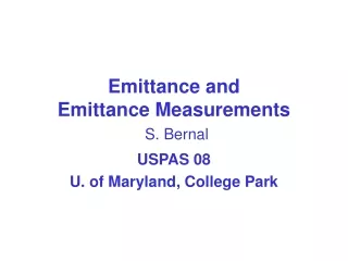
New emittance monitor beamline. A. Saa Hernandez, N. Milas, M. Rohrer, V. Schlott, A. Streun. Outline. New emittance monitor beamline Layout and working principle New vs. old beamline Basic elements: parameters and some concepts Plan B SRW simulations Different wavelengths

E N D
New emittance monitor beamline A. Saa Hernandez, N. Milas, M. Rohrer, V. Schlott, A. Streun TIARA mid-term meeting, CIEMAT, Madrid, 12 - 14 June 2012
Outline • New emittance monitor beamline • Layout and working principle • New vs. old beamline • Basic elements: parameters and some concepts • Plan B • SRW simulations • Different wavelengths • Interferometric method • Inclusion of mirror misalignments • Status TIARA mid-term meeting, CIEMAT, Madrid, 12 - 14 June 2012
focusing element visible/UV light: vertical polarizer finger absorber image plane = CCD camera horizontal (σ) polarization vertical (π) polarization electron beam (filament beam) filament beam spread function X-rays New emittance monitor beamline layout: exit window dipole BX-08 flat mirror finger absorber polarizer CCD camera toroidal mirror optical table measurement principle: π-polarization method TIARA mid-term meeting, CIEMAT, Madrid, 12 - 14 June 2012
Why a new emittance monitor beamline? • Increase sensitivity to small beam sizes (< 3 μm): • wavelength independent (only reflective elements are used) → allows shorter wavelengths (e.g. 266 nm) • allows interferometric method • Increase measurement precision → better magnification ratio • Full-time accessible → outside the SLS tunnel • Cross-check results with the use of different wavelengths and two measurement methods New beamline 6.985 flat mirror image plane 49° 0.144 interference obstacle z 0.350 S1 = 5.146 m S2 = 7.459 m y 45° θ M = -1.453 4.551 toroidal mirror 0.595 finger absorber x Old beamline flat mirror 3.88 image plane z 0.175 0.175 y 4.48 0.44 S1 = 5.095 m S2 = 4.055 m flat mirror M(λ=364 nm) = -0.841 finger absorber x TIARA mid-term meeting, CIEMAT, Madrid, 12 - 14 June 2012
S1 object Rx θ Rz S2 image Basic elements Toroidal mirror Reflects and focuses the beam Radii of the toroid chosen to correct astigmatism: for an incident angle θ = 22.5° → Rx = 6.592 m, Rz = 5.627 m → Fx = Fz = 3.045 m Parameters toroidal mirror Material SiC (silicon carbide) or Zerodur with coating (Al) R [mm] 38.1 ± 0.1 D [mm] ~ 20 Surface quality : Slope error ["] 0.2 Max. peak-valley [nm] 21 or better (λ/30, for λ = 632.8) RMS roughness [nm] < 4 TIARA mid-term meeting, CIEMAT, Madrid, 12 - 14 June 2012
peak-valley peak-valley Rp + Rv Rp Rv (Surface quality on mirrors) RMS roughness [nm] Max. peak-valley [nm] Slope error [ " ] TIARA mid-term meeting, CIEMAT, Madrid, 12 - 14 June 2012
Finger absorber Flat mirror Dipole BX-08 synchrotron radiation source reflects the beam protects mirror from excessive heat load by blocking x-rays and horizontally polarized visible/UV light Parameters finger absorber Parameters electron beam Parameters flat mirror 2.4 0.00086 0.2 5.5 5.5 Cu 60 4 Material Lx [mm] Lz [mm] E [Gev] ΔE/E I [A] ex [nm∙mrad] ey [pm∙mrad] L [m] Bz [T] Material fused silica with Al coating Max. peak-valley [nm] 21 or better (λ/30) Vertical obstruction angle [mrad] ± 0.45 Obstruction power (400 mA) 98% of 230 W Parameters bending magnet 3 1.4 Twiss and Dispersion parameters at source point 0.452 14.3 0.029 0 βx [m] βy [m] Dx [m] Dy [m] TIARA mid-term meeting, CIEMAT, Madrid, 12 - 14 June 2012
Plan B Replace toroidal mirror by a flat one and add a lens to focus = back to refractive optics 6.985 flat mirror image plane 49° interference obstacle 0.144 lens z 0.160 S1 = 5.358 m S2 = 7.289 m 0.190 45° y θ 4.551 0.595 flat mirror finger absorber x Parameters lens Material Fused Silica with Al coating CurvatureSpherical R1, R2, D Refractive index: n(λ=266 nm) 1.4997 n(λ =364 nm) 1.475 Surface errors: Max. peak-valley [nm] 38 RMS roughness [nm] 5.7 Adjust geometrical parameters of the lens to get magnification ratio ~ -S2/S1 e.g: For R1= R2 = 2.9 m, D=8 mm F(λ=266 nm) = 2.903 m → M(λ=266 nm) = -1.183 F(λ=364 nm) = 3.054 m → M(λ=364 nm) = -1.325 TIARA mid-term meeting, CIEMAT, Madrid, 12 - 14 June 2012
SRW simulations Signal at image plane (CCD camera) SRW (Synchrotron Radiation Workshop) code developed at SOLEIL and ESRF by O. Chubar and P. Elleaume Vertical polarization Horizontal polarization TIARA mid-term meeting, CIEMAT, Madrid, 12 - 14 June 2012
Vertically polarized light as a function of the emittance and beam size TIARA mid-term meeting, CIEMAT, Madrid, 12 - 14 June 2012
Different wavelengths For λ = 266, 340 and 498 nm Used to create look-up tables in monitor TIARA mid-term meeting, CIEMAT, Madrid, 12 - 14 June 2012
Interferometeric method 15 mm 20 mm 25 mm TIARA mid-term meeting, CIEMAT, Madrid, 12 - 14 June 2012
Interferometer vs. pure polarization method TIARA mid-term meeting, CIEMAT, Madrid, 12 - 14 June 2012
Tx Dy Ty R Dx Inclusion of mirror misalignments Dx horizontal offset Dy vertical offset Txhorizontal tilt Ty vertical tilt R rotation around mirror axis TIARA mid-term meeting, CIEMAT, Madrid, 12 - 14 June 2012
Inclusion of mirror misalignments 1 - Vertical offset 2 - Horizontal offset TIARA mid-term meeting, CIEMAT, Madrid, 12 - 14 June 2012
3 - Horizontal tilt TIARA mid-term meeting, CIEMAT, Madrid, 12 - 14 June 2012
4 + 5 - Rotation around optical axis and vertical tilt Both misalignments show the same pattern: mixing of the horizontal and vertical planes TIARA mid-term meeting, CIEMAT, Madrid, 12 - 14 June 2012
Status • Design almost finished • In contact with providers: delivery of all components expected for last months of the year • We need just a few more iterations to decide on the mirror alignment tolerances • Scheduled installation: 01/13 • Commissioning period: 01/13‐03/13 • Measurement period: 04/13‐06/13 … TIARA mid-term meeting, CIEMAT, Madrid, 12 - 14 June 2012
Some extra slides TIARA mid-term meeting, CIEMAT, Madrid, 12 - 14 June 2012
Can we correct the misalignment from the image analysis? • Vertical offset minimum when brilliance of the horizontal projection is maximum • Horizontal offset minimum when brilliance of the vertical projection is maximum • Rotation around optical axis is immediately recognizable by the plane mixing: peak asymetry in vertical projection, apearance of double peak in the horizontal projection Gaussian laser for mirror setup TIARA mid-term meeting, CIEMAT, Madrid, 12 - 14 June 2012
Inclusion of mirror misalignments 1 - Vertical offset TIARA mid-term meeting, CIEMAT, Madrid, 12 - 14 June 2012
2 - Horizontal offset TIARA mid-term meeting, CIEMAT, Madrid, 12 - 14 June 2012
3 -Vertical tilt TIARA mid-term meeting, CIEMAT, Madrid, 12 - 14 June 2012
3 -Horizontal tilt TIARA mid-term meeting, CIEMAT, Madrid, 12 - 14 June 2012
3 - Rotation around optical axis mixing the horizontal and vertical planes astigmatism will not be corrected any longer TIARA mid-term meeting, CIEMAT, Madrid, 12 - 14 June 2012