Download
1 / 21

E N D
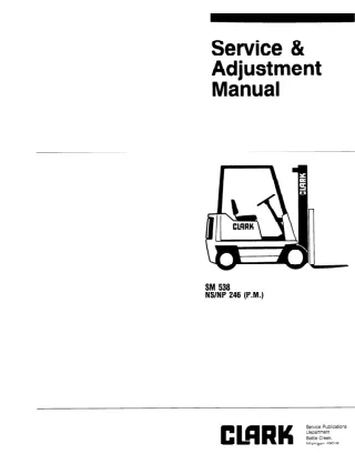
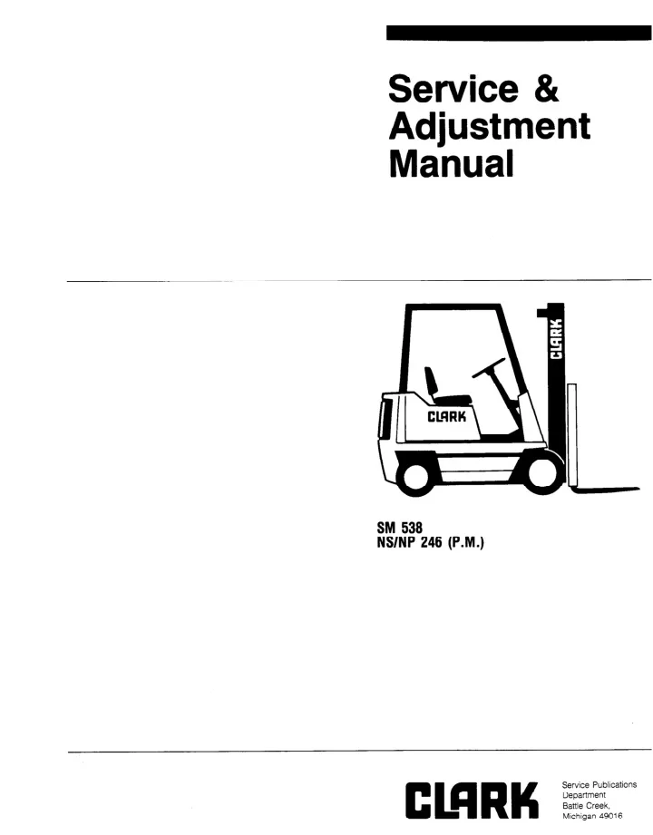
Service & Adjustment Manual SM 538 NS/NP 246 (P.M.) Copyrighted Material Intended for CLARK dealers only Do not sell or distribute
SERVICE MANUAL SM538 NP/NS 300 C&D CONTENTS PAGE GROUP FOREWORD HOW TO USE THIS MANUAL PICTORIAL INDEX SAFETY AND OPERATIONAL CHECKS RECOMMENDED PLANNED MAINTENANCE AND LUBRICATION SCHEDULE SAFETY SIGNS AND MESSAGES USER SAFE MAINTENANCE PRACTICES ii . . . III iv V vi vii . . . VIII PAGE GROUP PM-l 12-01-l 13-01-l 16-01-l 16-02-o 16-03-l 16-04-l 19-02-l 19-03-l 19-04-l 20-01-l 22-01-l 23-01-l 25-01-l 26-01-l 26-02-l 29-01-l 30-01-l 32-01-l 32-02-l 32-03-l 32-04-l 32-05-l 32-06-l 34-01-l 34-02-l 34-03-l 34-04-l 34-05-l 34-06-l 34-07-l 38-02-i 40-02-l PM Planned Maintenance Program 12 Battery Handling and Care 13 Accelerator Control 16 Electric Motor general maintenance 16 Drive motor 16 Lift Pump Motor 16 Steer Pump Motor 19 SCR Control ,Test, Equip., Proceedures 19 SCR, Symptom Charts 19 Control Panel 20 Drive Unit 22 Wheels and Tires 23 Brake 25 Caster Adjustment 26 Steering System 26 Power Steering Pump 29 Hydraulic Lift Pump 30 Main Hydraulic Valve 32 Tilt Cylinder Model C 32 Reach Cylinder Model C 32 Lift Cylinder Model D 32 Tilt Cylinder NP D 32 Tilt Cylinder NS D 32 Reach Cylinder NP D 34 Upright Removal Model C 34 Upright Maintenance Model C 34 Upright Lift Cylinder Model C 34 Pantograph Model C 34 Upright Removal Model D 34 Upright Maintenance Model D 34 Pantograph NP D 38 Machine Jacking & Blocking 40 Truck Data, Specifications SM538 i Copyrighted Material Intended for CLARK dealers only Do not sell or distribute
FOREWORD Clark Equipment Company welcomes you to the growing group of professional people who own, operate and maintain Clark lift trucks. This manual will familiarize you with service maintenance and overhaul information about your new truck. It has been especially prepared to help you maintain your Clark lift truck in an efficient and safe operating condition. Regular, correct maintenance and care of your lift truck is not only important for full and efficient truck life; it is essential for your safety. A faulty lift truck is a potential source of danger to the operator, and to other personnel working near it. The importance of maintaining your lift truck in a safe operating condition by servicing it regularly and, when necessary, repairing it promptly cannot be emphasized too strongly. To assist you in keeping your lift truck in good operating condition, this manual includes an outline of planned maintenance (PM) procedures that are considered essential to the life and safe performance of your truck. Brief procedures for inspections, operational checks, cleaning, lubrication, and adjustments are included for your reference. Clark recommends that a planned maintenance and safety inspection program (PM) be performed by a trained and authorized mechanic on a regular basis. The PM program provides the opportunity to make thorough inspections and checks on the safe condition of your truck. Necessary adjustments and repairs can be done during the PM, which will increase the life of components and reduce unscheduled downtime. The need for major adjustments, repairs, or replacements is found and corrections made as required; not after failure has occurred. SM538 ii Copyrighted Material Intended for CLARK dealers only Do not sell or distribute
HOW TO USE THIS MANUAL This manual is intended to be used by persons who are trained and authorized to do lift truck maintenance. The recommended procedures for routine servicing and adjustments as well as for removal and overhaul of major components of the truck are outlined. It is written to show and describe the adjustment, removal, disassembly, inspection, repair, and assembly steps that are normally required to service these components. The detailed procedures are arranged in sequence by numbered GROUP and Section. The GROUP numbers are the same as the component group in the Master Parts Book. Each GROUP has its own Table of Contents, so that you can find the various topics within more easily. If you cannot find a topic in the Table of Contents, check the Index at the back of the manual. Component specifications, information notes and safety messages are included at the proper step of each procedure. To be better prepared to do the necessary service work, please take time to read the entire procedure, including any special instructions, before doing any work. Specifications of selected truck components are included at the back of the manual for easy reference. Also refer to the Operator’s Manual, located on the truck, for additional information and instructions on the operation and maintenance of your truck. If you have need for more information on the care and repair of your truck, please contact your authorized Clark dealer. Clark NOTICE - The descriptions Equipment Company reserves the right to make improvements and without incurring obligation. or revisions. and specifications included in this manual were in effect at the time of printing. and changes in specifications Please check with your authorized CLARK dealer for information or design, without notice on possible updates 0 Clark Equipment Company 1987 SM538 iii Copyrighted Material Intended for CLARK dealers only Do not sell or distribute
PICTORIAL INDEX NP/NS 30Tquf;row Aisle (NP) (NS) = Straddle pantograph) = Pantograph (no 1 _ Overhead guard 2. Overhead guard rear post 3. Upri ht assembly 4. Loa 2 backrest extension 5. Fork carria 9 e 6. Load whee s (NP model shown) 7. Load forks 8. Pantograph mechanism 9. Swivel caster 10. Battery compartment (NP only) SM538 iv Copyrighted Material Intended for CLARK dealers only Do not sell or distribute
SAFETY AND OPERATIONAL CHECKS PM Interval: A=8 B = 50 - 250 hours. or everv month c=450- 500 ho&, D = 900 - E = 2000 hours, or every year - 10 hours, or daily or e@ry 3 months 1000 hours, or every 6 months DAILY MAINTENANCE CHECKS Check truck for obwous damage and leaks. Check / clean battery terminals Check electrolyte level. Check capacity, warning plates, decals Check condition of tires and wheels. Remove SM538 v Copyrighted Material Intended for CLARK dealers only Do not sell or distribute
RECOMMENDED AND LUBRICATION PLANNED MAINTENANCE SCHEDULE Lubrication Standard CHECK OR LUBRICATE (1 -W - Guide rollers (1 -A) \ ) Fork fl>6-F (1 Cable sheave (8- J) -A) Pantograph 43-J) Lift chain & Upr. rollers (1-K) - (1-E) Batt. rollers 51&6-F) Cont. Handle f 4 ‘:-l_~~~~s~~~r?(?J~ 4, Trans. case ( 2 -G) (‘Steer Trans. yoke (1 -A) / ,,I’_ Hyd.oilfilter(D)~~'~i &8-J) --_( Pedal shaft 1 -A) Swivel bar. I gears (7-J) - Eh:;'Ll 150 hours 500 hours 1000 hours 2000 hours I’ I r Lubricants (6) - SAE 20 Engine oil (1) - MPl- multi grease NL c? urpose 1 # 1 (2) - GL5 - transmission lubriiant APl GL5 (7) - 886785 Spray lubricant (3) - CCa-;hgi$xicant (8) - Dry graphite (5) - MS68 Hydraulic oil -Method A - Use standard lube gun II for flush type fittings (C) - Clean in solvent and re-oil D) - Change filter E) - Remove, clean and repack F) - Apply light film G) - Drain, flush and refill H) - Repack bearing J) - Clean and lubricate (K) - Apply to channel of rail B - Use lube gun and adaptor I SM538 vi Copyrighted Material Intended for CLARK dealers only Do not sell or distribute
SAFETY SIGNS AND SAFETY MESSAGES Improper or careless techniques cause accidents. Don’t take chances with incorrect or damaged equipment. Read and understand the procedures for safe operation and maintenance outlined in this manual. STAY ALERT! Follow safety rules, regulations and procedures. Accidents can be avoided by recognizing dangerous procedures or situations before they occur. DRIVE AND WORK SAFELY and follow the safety signs and their messages displayed on the truck and in this manual. SAFETY SIGNS and MESSAGES are placed in this manual and also on the lift truck to provide instructions and to identify specific areas where potential hazards exist and special precautions should be taken. Be sure you know and understand the meaning of these instructions, signs and messages. Damage to the truck or death or serious injury to you or other persons may result if these messages are not followed. NOTICE This message is used when special information, instructions or identification is required relating to procedures, equipment, tools, pressures, capacities and other special data. IMPORTANT ensure a correct action or to avoid damage to or malfunction of the truck or a component. This message is used when special precautions should be taken to CAUTION This message is used as a reminder of safety hazards which can result in personal injury if proper precautions are not taken. WARNING This message is used when a hazard exists which can result in injury or death if proper precautions are not taken. DANGER This message is used when an extreme hazard exists which will result in death or serious injury if proper precautions are not taken. SM538 vii Copyrighted Material Intended for CLARK dealers only Do not sell or distribute
USER SAFE have been prepared and government MAINTENANCE PRACTICES The following instructions from current industry standards applicable to industrial truck operations and maintenance. procedures specify conditions, accepted practices that aid in the safe mainte- nance of industrial trucks. They are listed here for the reference and safety of all workers during maintenance operations. understand these instructions maintenance procedures before attempting to do any repair work. When in doubt of any mainte- nance procedure, please contact CLARK dealer. 9. Before working on engine fuel system of LP- gas powered trucks, close LP-gas cylinder valve and run engine until there is no more fuel in the system and engine stops running. not run, close LP-tank valve and vent fuel slowly in a safe area. safety These recommended methods, and If engine will 10. Operation of the truck to check performance must be conducted in an authorized, safe, clear area. Carefully and the specific read and 11. Before Starting To Drive Truck: your local a) Be in operating position. b) Disengage clutch on manual transmissions, or apply brake on trucks with powershift transmission and electric trucks. c) Put directional control in neutral. d) Start engine or turn on power. e) Check functioning of lift and tilt systems, directional and speed controls, steering, brakes, warning devices, and attachments. 1. Powered industrial trucks can become hazard- ous if maintenance is neglected. suitable maintenance facilities, trained personnel, and procedures must be provided. Therefore, 2. industrial trucks shall be done in conformance with the manufacturer’s recommendations. Maintenance and inspection of all powered any load handling 12. Before Leaving The Truck: 3. A scheduled planned maintenance, lubrication, and inspection program shall be followed. a) Stop truck. b) Fully lower the load engaging upright, carriage, forks, or attachments. c) Put directional control in neutral. d) Apply the parking brake. e) Stop the engine or turn off power. f) Turn off the control or ignition circuit. g) Put blocks at the wheels, if truck is on an incline. nii . 4. Only trained and authorized personnel shall be permitted to maintain, repair, adjust, and inspect industrial trucks, and in accordance manufacturer’s specifications. with the 5. fumes, and keep shop clean and floor dry. Properly ventilate work area, vent exhaust 6. Avoid fire hazards and have fire protection equipment present in the work area. Do not use an open flame to check for level, or leakage of fuel, electrolyte, or coolant. Do not use open pans of fuel or flammable cleaning fluids for cleaning parts. 13. Handle LP-gas cylinders with care. Damage such as dents, scrapes, dangerously weaken the tank and make it unsafe for use. or gouges may 7. Before Starting Work On Truck: 14. Brakes, steering mechanisms, control mechanisms, warning devices, lights, governors, lift overload devices, guards and safety devices, lift and tilt mechanisms, articulating axle stops, and frame members must be carefully and regularly inspected and maintained condition. a) Raise drive wheel(s) off of floor or disconnect power source and use blocks or other positive truck-positioning devices. b) Put blocks under the load engaging means, innermast( or chassis before working on them. c) Disconnect battery before working on the electrical system. in a safe operating 8. gasoline powered trucks with gravity-feed systems, be sure fuel shutoff valve is closed. Before working on engine fuel system of fuel SM538 viii Copyrighted Material Intended for CLARK dealers only Do not sell or distribute
USER SAFE MAINTENANCE PRACTICES Care must be taken to assure that all replacement parts, interchangeable with the original parts and of a quality at least equal to that provided in the original equipment. Parts, including installed per the manufacturer’s Always use genuine CLARK or CLARK-approved parts. 24. Special trucks or devices designed and area operation 15. approved for hazardous receive special attention to ensure that main- tenance preserves the original, approved safe operating features. including tires, are must tires, are to be procedures. 16. Fuel systems must be checked for leaks and condition of parts. Extra special consideration must be given in the case of a leak in the fuel system. Action must be taken to prevent the use of the truck until the leak has been corrected. 25. When removing tires, follow industry safety practices. Most important, deflate pneumatic tires completely prior to removal. Following assembly of tires on multi-piece rims, use a safety cage or restraining device while inflating. 17. inspected and maintained in conformance with good practice. Tilt and lift cylinders, valves, and other similar parts must be checked to assure that “drift” or leakage has not developed to the extent that it would create a hazard. All hydraulic sytems must be regularly when removing heavy the truck, upright, etc. Be sure that lifting 26. components counterweight, and handling equipment is of the correct capacity and in good condition. Use special care from such as 18. When working on hydraulic system, be sure the engine is turned off or battery disconnected on electric trucks, upright is in its fully-lowered position, and hydraulic pressure relieved in hoses and tubing. WARNING -- Always put blocks under the carriage and upright rails when necessary to work with upright in an elevated position. NOTICE -- You should also be familiar with additional operating and maintenance instructions contained publications: safety in the following 19. The truck manufacturer’s capacity, operation and maintenance instruction plates, tags, or decals must be maintained in legible condition. ANSVASME B56.1 - 1983: Safety Standard for Low Lift and High Lift Trucks (Safety Code For Powered Industrial Trucks). Published by: Society of Mechanical Engineers, Center, 345 E. 47th Street, New York, N.Y. 10017. United Engineering 20. protective connections must be inspected and maintained in conformance with good practice. Special attention must be paid to the condition insulation. Batteries, motors, controllers, limit switches, devices, electrical conductors and NFPA 505-l 982: Powered Industrial Trucks: Areas of Use, ,Maintenance Available from: National Fire Protection Assoc., Inc., Batterymarch Park, Quincy, MA 02269. Fire Safety Standard Type Designations, and Operation. for of electrical 21. To avoid injury to personnel or damage to the equipment, consult procedures in replacing contacts on any battery connection. the manufacturer‘s General Industry Standards, OSHA 2206: OSHA Safety and Health Standards (29 CFR 1910), Subpart N-Materials Handling Section 1910.178 Powered Industrial Trucks. For sale by: Superintendent Government Printing Office, Washington, 20402. and Storage, 22. condition to minimize fire hazards and help in the detection of loose or defective parts. Industrial trucks must be kept in a clean of Documents, U.S. D.C Modifications and additions that affect 23. capacity and safe truck operation must not be done without the manufacturer’s approval. Capacity, operation and maintenance instruction plates, tags or decals must be changed accordingly. prior written SM538 ix Copyrighted Material Intended for CLARK dealers only Do not sell or distribute
PM - PLANNED MAINTENANCE PROGRAM Disconnect battery from truck receptacle before working on electrical components. Always (hard) hat in industrial plants and in special work areas where protection required. wear safety glasses. Wear a safety CONTENTS PG is necessary or General Visual Inspection Functional Test Drive The Truck Air Cleaning Critical Fastener Torque Check Lubrication, Fluids and Filters : 5 8 Tests HOW TO PERFORM INSPECTIONS THE PM PERIODIC AND MAINTENANCE 11 11 11 VISUAL First, perform a visual inspection its components. of any obvious problems. Check for loose fasteners and fittings. INSPECTION of lift truck and Walk around truck and take note damage and maintenance GENERAL A planned routine inspections long l,ife and trouble-free truck. Make and keep records of your inspections. Use these records to help establish the correct PM intervals for your application maintenance required to prevent major problems from occurring during operation. maintenance of regular, is important for operation of your program and lubrication lift and to indicate L PM Report Form As an aid in performing inspections, TRUCK PLANNED form. Copies of this form may be obtained your authorized CLARK dealer. that you use this form as a checklist and to make a record of your inspection and documenting your PM Clark has prepared MAINTENANCE an “ELECTRIC REPORT” from We recommend Check to be sure all capacity, safety, and warning plates or decals are attached and legible. and truck condition. NOTICE The periodic this manual are intended to be used with PM report form. They are arranged maintenance work that are done in a logical and efficient sequence. maintenance procedures outlined in NAMEPLATES & DECALS Do not operate a lift truck with damaged or missing decals and nameplates. them immediately. They contain important information. in groupings of Replace A check mark or entry is made on PM Report Form when PM is performed. coding system for indicating repairs and/or adjustments. Please importance of needed note special When you have finished to give a copy of report to designated person responsible PM inspections, be sure authority or for lift truck maintenance. Do unless not make authorized repairs or adjustments to do so. For safety, it is good practice to: Remove all jewelry (watch, rings, bracelets, etc.) before working on the truck. SM538 PM - 1 Copyrighted Material Intended for CLARK dealers only Do not sell or distribute
Inspect truck for any signs of external leakage: transmission fluid, etc. Check for hydraulic oil leaks and loose fittings. DO NOT USE BARE HANDS TO CHECK. Oil may be hot or under pressure. SAFETY NOTE HYDRAULIC FLUID PRESSURE Do not use your hands to check for hydraulic leakage. Fluid under pressure can penetrate your skin and cause serious injury. Be sure that driver’s overhead guard, load backrest extension, finger guards, shields, padding, and any other safety devices are in place, undamaged, and attached securely. SAFETY NOTE Uprights can drop suddenly. Look at upright, but keep hands out. NOTICE - For trucks equipped with spark- enclosed construction polyurethane tires: Check ground strap for security of attachment and wear damage. (EE), or with Inspect upright assembly: rails, carriage rollers, lift chains, lift and tilt cylinders, reach mechanism and reach cylinder. Look for obvious maintenance problems, damaged or missing parts. Check for any loose parts or fittings. leaks, any damaged or loose rollers. and rail wear (metal flaking). Carefully check lift chains fcr rust and corrosion, cracked or broken 11~11 stretching, etc. Check that lift and carriage chains are correctly adjusted to have equal tension. Check that lift chain anchor fasteners and locking means are in place and tight. wear and Then, check all of the critical components that handle or carry the load. Check for 1 Overhead Guard ‘qr. Upright Load Backrest Extension r XI Be sure all safety guards and chain retainers are in place and not damaged. and cylinder retainers. connections. Inspect carriage stops Check all welded Carriage -_ Forks Load Wheel I Outrigger I Inspect all lift line hydraulic connections for leaks. Check lift cylinder rod, tilt cylinder rod and reach cylinder rod for wear marks, grooves, scratches. Check cylinder seals for leaks. and Check overhead guard for damage. Be sure that it is properly positioned and all mounting fasteners are in place and tight. IMPORTANT Uprights and lift chains require special attention and maintenance them in safe operating condition. Refer to Lift Chain Maintenance additional information. Check load backrest for damage. Inspect welds on carriage and load backrest for cracks. Be sure that mounting fasteners are all in place and tight. to maintain section for - If load backrest has been NOTE removed, a bolt and washer must be in place on each end of top fork bar to act as a fork stop. SM538 PM - 2 Copyrighted Material Intended for CLARK dealers only Do not sell or distribute
Forks blade of fork with 4” surface against blade. Put a 24” carpenters square on top of block and against shank. Check fork 20” above blade to be sure it is not bent more than 1 inch maximum. Inspect load forks for cracks, breaks, bending and wear. The fork top surfaces should be level and even with each other. between both fork tips should be no more than 3% of fork length. The height difference If fork blades are obviously bent or damaged, have them inspected by a trained maintenance person. Inspect fork latches. damaged or broken and operate freely and lock correctly. Check fork stop pins (or bolt and washer) for secure condition. Be sure they are not FORK LENGTH X .03 = HEIGHT DIFFERENCE - 10% of ‘A’ max. wear Check amount of wear at heel of fork. WARNING If fork blade at the heel is worn down by more than lo%, load capacity and the fork must be replaced. .9 = 1.575 MINIMUM PERMITTED FOR AN ORIGINAL THICKNESS OF 1.75 INCHES). is reduced (IE. 1.75 X THICKNESS FORK Sh lank Inspect forks for twists and bends. To check, put a 2” thick metal block, at least 4” wide by 24” long on SM538 PM - 3 Copyrighted Material Intended for CLARK dealers only Do not sell or distribute
FUNCTIONAL Be sure that all controls and systems are functioning correctly. TESTS Wheels and Tires Check stabilizing Remove Inspect tires for excessive “chunking out”, and bond failure between tire and rim. condition caster objects of drive wheel, that are embedded wheel and of load wheels. and tire, of Test all warning safety equipment are properly mounted and working correctly. devices, and accessories. horn, lights, and other Be sure they in treads. wear and breaks or Press horn button to check horn function. or any other part does not operate, and have it repaired before truck is put back into operation. If horn report failure Check all wheel lug nuts or mounting fasteners to be sure none are loose or missing. Have missing fasteners replaced and loose fasteners tightened to correct torque before operating truck. Operate brake pedal, all hydraulic controls: Ii’ reach, and auxiliary (if installed), control accelerator and directional steering system. Be sure all controls freely and return to neutral properly. operator control, hacd an? operate \I v+l \I of foot brake mechanism. then release foot-operated adjusted, foot pedal should move to brake-applied position by spring action when released. pedal binds or does not operate lubricant to linkage at pivot points. I I SAFETY working NOTE on wheels and qualified Personnel must be trained and tire maintenance. and tires to do wheel I I Check function Apply, pedal. When correctly If foot apply freely, Fully rotate operators release, to check for free movement. control handle and then SM538 PM - 4 Copyrighted Material Intended for CLARK dealers only Do not sell or distribute
Check directional both ways, function. to operate truck until repair has been made. control by rotating control handle releasing handle, Report any malfunction. then for correct Do not attempt Be sure lift and tilt contol feature of control handle moves freely and returns position when released. to center or neutral begin from a Before safe condition. starting a lift truck, Check to see that: Brake is applied (foot is not on brake pedal). Forks are fully lowered to floor. You are familiar with how all controls function. All controls are in neutral or other correct position. Check battery discharge should register in green area when key switch is ON. Also, check function indicator when making a battery load test, below. indicator. The indicator of battery discharge Turn key switch ON. Battery Load Test Check battery condition control in full back-tilt run against loading of bypass relief pressure for a few seconds. Watch battery discharge The needle should stay in green area. falls into red area, battery is faulty or charge level is low and battery must completing other electrical parts of PM. by holding operator hand position, allowing pump to indicator. If needle be recharged tests and performance before BEFORE DO THESE DRIVING TESTS: THE TRUCK, Check hour meter operation. release brake (step on brake pedal). pump and hourmeter Watch for movement opening. Report any malfunction With key switch ON, Test for correct function on LIFT portion of operator control handle. key switch ON. Slowly control handle (RAISE position). should start to run as handle moves from neutral position. Push handle forward (LOWER position) until upright starts to lower. running. Pump motor should handle is moved to “lower” position. of lift pump motor switch The steer operating. in the dial or damage. Turn should of indicator begin pull back on operator The pump motor Turn key switch off and Power steer motor should eight (8) second delay. remove foot from brake. stop running Pump not operate when will stop after an Write form. hourmeter reading on PM report If operator control handle movement before pump starts, running when handle position switch needs repair or adjustment. is excessive or if pump does not stop returns to neutral, spool Test for correct function REACH, and AUX function control. of motor switch for TILT, Slowly move tilt control portion of operator control handle forward and then backwards, while SM538 PM - 5 Copyrighted Material Intended for CLARK dealers only Do not sell or distribute
pressing picture switch prevents LIFT motor from turning ON). on blue side of toggle switch (showing of TILT on switch). (Pressing this blue This movement should activate tilt cylinder. Repeat depressing picture of REACH on switch) and pulling back or pushing forward on control handle at same time. Refer to discussion above if handle movement or switch action is not correct. test for reach yellow side of toggle switch (showing control, if installed, by Check function of parking brake microswitch. key switch ON and parking brake applied (foot off brake pedal), move operator FORWARD position. Rotate handle for FWD direction slowly _ The drive motor should not operate. If it does, microswitch parking brake linkage is not adjusted Also, check REVERSE handle. With control operator handle control to Turn key switch OFF and apply brake. Steer pump should stop after an eight (8) second delay. on the correctly. rotation NOTICE steering for abnormal any changes excessive freeplay (looseness) when turning or maneuvering inspection and servicing. - The steering linkage should be inspected looseness in steering system, steer wheel and direction of periodically Check for Hard steering, or unusual sounds indicates a need for and damage. action. Check brake switch and braking action. brake by stepping operators control handle forward. Then, apply brake by taking foot off brake pedal. The brake should turn drive motor off and stop and hold truck from further movement. Release Rotate on brake pedal. to move truck slowly Never operate steering a truck which system fault. has a To check brake holding capability park truck on a grade and apply brake. The brake should hold a lift truck with rated load on a 15% grade. When brake pedal should not drag. and adjustment, is released, brake CAUTION if brake - Do not operate is not operating a lift truck properly. Test for correct function of power steering pump switch and system. Turn key switch ON, and release brake. The steer pump should begin operating. With truck not moving, check steering system by moving steering handwheel then in a full left turn. Return handwheel wheel) to straight-ahead components should operate steering wheel is turned. pressure relief valve to by-pass when steer wheel hits stops. The steer pump and motor should not stall or exhibit excessive loading. steering system relief pressure malfunctioning. in a full right turn, and (steer position. The steering smoothly Listen for steering when If it does, power valve may be SM538 PM - 6 Copyrighted Material Intended for CLARK dealers only Do not sell or distribute
TEST DRIVE THE TRUCK NOTE - It is recommended be conducted with a rated capacity possible. position. controlled direction. handle backward to FORWARD position. The truck should stop and Repeat test by rotating operator control slow to a smooth, accelerate in opposite that these tests load, if Check handle must acceleration There should either acceleration acceleration while move of operator speed ‘range smoothly and return without be no restriction or deceleration. control control tests. throughout binding. Test truck for general drive train function, by driving truck in both forward and reverse directions first in a straight then, slowly, through a series of full right and left turns. correct operation and conducting easily stroke, It and line and to movement on Check all around to be sure that your intended path of travel is clear pedestrians. Test brake (drive motor cut-off) switch. FORWARD (or in REVERSE) While holding operator creep-speed position, pedal. The braking action should interrupt power to drive motor and stop truck. Depress brake pedal and move control handle to NEUTRAL and then to FORWARD (or REVERSE). should start again moving truck. Drive truck of obstructions and at creep speed. handle steady in foot from brake control remove Test for correct function of SCR traction control. Check PLUGGING. CREEP SPEED, 1A RANGE, and The drive motor 1. Check CREEP SPEED and 1A RANGE while driving truck in a straight line in both FORWARD and REVERSE directions. should be obtained at beginning after rotating operator amount. CREEP of SCR RANGE handle SPEED control a slight 1A RANGE rotated farther RANGE RANGE contactor as truck goes out of SCR RANGE and into 1A. All speed changes should increasing and decreasing unusual drive train noises or actions of controls and drive train components. - When operator , truck should and make a smooth for maximum closes, there should be very little surge control accelerate transition speed. handle in SCR into 1A As 1A is travel be smooth Listen for any while speed. Retest brake operation brakes several times while driving truck. 1) Check for quick pedal return,and for full stopping without pulling to one side 2) Listen for brake squeal and other abnormal noise. by applying and releasing Stop truck with brake. Note any unusual reactions in driving or braking performance, adjustment. and need for 2. PLUGGING provides controlled plugging deceleration, speed opposite is determined rotated . is an SCR control function for reversing direction conditions. control should or gradual stop of travel from any in one direction, and direction. Plugging by amount operator control handle is which under Check steering control operation. in a straight line. speed) through a series of full right and left turns. The truck must drive in a straight drifting toward either response and smoothness effort must be same in either direction. First, drive truck of travel Then, drive SLOWLY (creep A correctly-adjusted result in a smooth line without Check of operation. steering Turning side. acceleration speed and distance in NOTICE - It is recommended also be conducted available. that following tests load, if with a rated capacity Check PLUGGING function first at a slow speed. If operating correctly, then test at full speed. drive truck in FORWARD operator control handle accelerate to desired travel speed. rotation of operator control First, Rotate truck direction. and Test for general drive train operation Drive truck at various conditions, in both FORWARD directions. Test and noises. operating and REVERSE NEUTRAL allow Then, reverse handle to REVERSE to speed and shifting from to SM538 PM - 7 Copyrighted Material Intended for CLARK dealers only Do not sell or distribute
Thank you very much for your reading. Please Click Here. Then Get COMPLETE MANUAL. NO WAITING NOTE: If there is no response to click on the link above, please download the PDF document first and then click on it.
WARNING FALLING FORKS FORWARD, then back to “N”. Next, test shift from “N” to REVERSE, then back to “N”. Check for positive control action when changing directions. Do not walk or stand under raised forks. The forks can fall and cause injury or death. Listen for clunking, squealing, grinding, scraping or other unusual noise. Check for vibration. Listen for wheel bearing or other specific running noise. Observe upright assembly: rails, roilers, carriage, lift chains and cylinder as they move. Check for binding or excessive between carriage and upright rails and rollers. Listen for abnormal noises. If there is excessive clearance between rails and channels,a need for upright roller adjustment is indicated. carriage bind or hesitate when lowering, this indicates either damaged rollers or incorrect roller adjustment. Lift mechanism and controls freeplay (looseness) NOTE - It is recommended that these tests be conducted with a rated capacity load (RATED LOAD is shown on nameplate), if possible. If rails or Test operation of hydraulic system and upright. SAFETY NOTE Check upright for excessive downdrift. fork carriage in an intermediate position. that it holds its position and raises or lowers smoothly from any height position. carriage does not hold its position when stopped , upright may have too much downdrift due to wear of cylinder seals. Conduct an upright cylinder downdrift test, with rated load, as needed. Stop the Check BE SURE THERE IS ADEQUATE OVERHEAD CLEARANCE BEFORE RAISING UPRIGHT. If the fork Test tilt control. Check for excessive tilt cylinder drift. Stop carriage at a position near vertical. Check that carriage holds its position without moving forward. If you observe forward movemer,. (drift), or have a report of a tilt drift problem, check tilt cylinder for too much drift. Check correct fork height adjustment (also carriage chain adjustment). Tilt forks to vertical position and fully lower carriage. The forks should stop and be held approximately [13 mm] .50 inch above floor. If forks hit floor, carriage adjusted. lift chains should be Cycle (raise to full height and then lower) upright at both slow and fast speed, with forks tilted slightly backwards. Watch upright assembly as it rises. All movements of upright, fork carriage, and lift chains must be even and smooth, without binding or jerking motion. Watch for chain wobble or looseness; chains should have equal tension and move smoothly without noticeable wobble. Auxiliary function control If truck is equipped with an attachment, check control for correct function by briefly operating attachment. When you have completed operational tests, park and leave truck according to standard shutdown procedures. Check for correct function of lift control portion of operator control handle and main hydraulic valve. Listen for abnormal noise in hydraulic valve, main hydraulic pump, and system components. Be sure to make a record of all maintenance and operating problems you find. If maximum fork height is not reached, this indicates there is an inadequate (low) oil level in hydraulic sump tank, or severe binding within upright. Battery Compartment Inspection SM538 PM - 8 Copyrighted Material Intended for CLARK dealers only Do not sell or distribute
Degreaser (or equivalent to MS-l 80 Freon TF Degreaser and Cleaner). Turn key switch OFF. truck receptacle by pulling on red emergency battery disconnect lever. Make sure lower arm of lever is spaced correctly to engage battery cable end of quick disconnect connector and that lever moves freely without binding and returns to rest position. Disconnect battery from Turn key switch OFF. truck receptacle. cover. Disconnect battery from Remove lower control panel Discharge capacitor. Use an insulated tool, such as a screwdriver with plastic or wood handle, to short between terminals. Inspect condition of battery connector. spring-loaded terminal and retaining tab for poor connection due to burning, bad crimp, or loose or broken retainer. Check molded body for damage from overheating, burning and chips or cracks. Clean all corrosion from contacts, as necessary. Check Inspect SCR controls for clean condition. for oily dirt buildup on contactors, SCR control card, capacitor, etc. Inspect all controls wiring and terminals for any obvious damage. Look for cracks or worn areas in wiring insulation. Check for loose connections at controls terminals. necessary. Check Inspect spring-loaded connectors in truck battery receptacle. Look for looseness, burned pans and other damaged areas due to excessive Refer to checks noted above. conditions are evident, replace connectors. Air clean, as heat. If any of above AIR CLEANING Inspect condition of battery and cables. battery cables for wear or other damage, and routing clear of interference (rubbing) with other components. Be sure that cable terminals are tight and clean. Clean off minor deposits of corrosion that you find on battery. Check Always maintain a lift truck in a clean condition. Do not allow dirt, dust, lint, or other contaminants to accumulate on truck. Keep truck free from leaking oil and grease. Wipe up all oil spills. Keep controls and floorboards clean, dry, and safe. A clean truck makes it easier to see leakage, loose, missing or damaged pans, and will help prevent fires. A clean truck will run cooler. IMPORTANT - Never wash battery when it is in truck. The environment in which a lift truck operates will determine how often and to what extent cleaning is necessary. For example, trucks operating in manufacturing plants which have a high level of din or lint (e.g., cotton fibers, paper dust, etc.) in air or on floor, will require more frequent cleaning. If air pressure does not remove heavy deposits of grease, oil, etc., it may be necessary to use steam or liquid spray cleaner. Check battery post terminals for corrosion and damage. Clean all corrosion from cable end and battery post. Check tightness of cable and post terminals. If necessary, check state-of-charge condition of battery. Take a specific gravity test of electrolyte with a hydrometer. Be sure to check a minimum of six battery cells. LIFT TRUCKS EVERY OFTEN SHOULD BE AIR AND CLEANED OTHERWISE AT AS Check electrolyte level of battery. Add distilled water, as required, to fill each cell to correct level. Check to be sure vent holes in all battery cell caps are open. If cap vents are plugged with corrosion, remove them and wash in a solution of baking soda and water. PM INTERVAL, AS REQUIRED. Air cleaning should be done using an air hose with special adapter or extension having a control valve and nozzle to direct air properly. Use clean, dry, low-pressure compressed air; restrict air pressure to [207 kPa] 30 psi, maximum. suitable eye protection and protective clothing. Wear Motor SCR Controls Inspection CAUTION- IMPORTANT Upright assembly; drive unit; battery, Air clean cables, switches and wiring harness; SCR controls and wiring; drive, lift, and steer motors; and steer linkage. CLEANING AND INSPECTION OF ELECTRICAL COMPONENTS Do not clean electrical components with steam. Only approved solvents should be used to clean controls components. Use Clark and #1801146 SCR CRITICAL CHECK FASTENER TORQUE SM538 PM - 9 Copyrighted Material Intended for CLARK dealers only Do not sell or distribute
B - Pumping fluid out by using truck hydraulic system. This method may be used most easily and satisfactorily for routine changes of fluid. Fasteners in highly loaded (critical) components can quickly fail if they become loosened; loose fasteners can cause damage or failure of components. For safety, it is important that correct torque be maintained on all critical fasteners of components which directly support, handle or control load, and protect the operator. also, Hydraulic Oil Filter Remove and replace hydraulic system fluid filter per recommended PM schedule, or as may be required by truck operating conditions and usage. Install a new oil filter. Be sure to follow installation instructions printed on filter. Check for leaks after installation of filter. Also, check that hydraulic line connections at filter adapter correctly. Check torque of critical items, including: Overhead guard; drive unit mounting; drive wheel mounting; stabilizing caster mounting: load wheel mounting; load backrest extension; tilt cylinder mounting and yoke; reach mechanism and mounting; upright mounting & components. are tightened LUBRICATION, FILTERS FLUIDS AND IMPORTANT Always use genuine CLARK parts. Sump Tank Breather Maintenance HYDRAULIC SUMP Remove sump tank fill cap/breather and inspect for excessive (obvious) contamination and damage. Clean or replace fill recommended PM schedule or as required by operating conditions. Check hydraulic sump tank fluid level. Correct fluid level is important for proper hydraulic system operation. Low fluid level can cause pump damage. Overfill can cause loss of fluid or lift system malfunction. cap/breather, per ACCESS TO THE DRIVE UNIT Hydraulic fluid expands as its temperature rises. Therefore, it is preferable to check fluid level at operating temperature (after approximately minutes of truck operation). first park truck on a level surface and apply brake. Retract reach mechanism and lower fork carriage fully down. Pull dipstick out, wipe it with a clean wiper and reinsert it fully into dipstick tube. Remove dipstick and check oil level. Keep oil level above LOW mark on dipstick recommended hydraulic fluid only, as required. DO NOT OVERFILL. To reach drive unit check points (oil level/fiQr plugs and drain plugs) , it is ncessary to elevate rear of truck. 30 To check fluid level, Refer to Machine Jacking and Blocking section for additional information on raising rear of truck safely. by adding Check condition of hydraulic fluid (age, color or clarity, contamination, etc.). Change (replace) oil, as necessary. Hydraulic Fluid and Filter Change Drain and replace hydraulic sump fluid every 2000 operating hours, or sooner, as required. hydraulic oil filter at every oil change. sump tank breather/fill cap every 1000 operating hours. Replace Replace There is no drain plug in hydraulic sump tank. The hydraulic fluid can be changed by one of following methods: A - Removal of hydraulic assembly and pumping fluid out by suction using a separate pump and hose. sump tank cover SM538 PM - 10 Copyrighted Material Intended for CLARK dealers only Do not sell or distribute