Download
1 / 28
280 likes | 303 Views
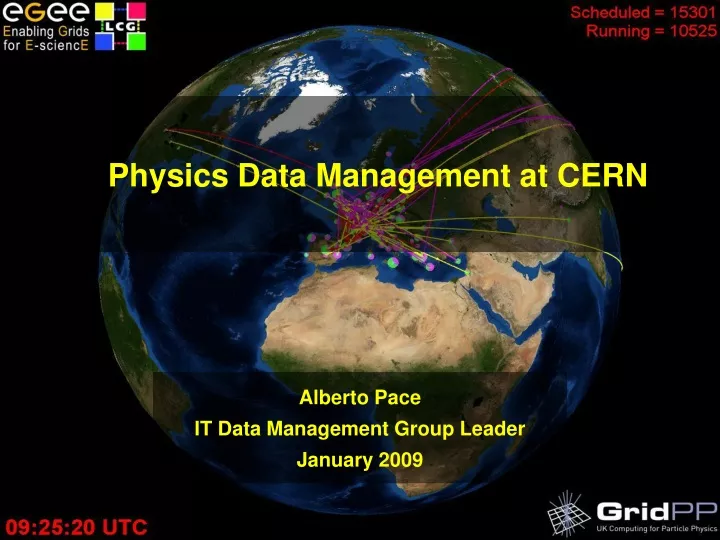
Physics Data Management at CERN. Alberto Pace IT Data Management Group Leader January 2009. View of the ATLAS detector (under construction). 150 million sensors deliver data … … 40 million times per second. Distribution of CERN users (Feb 2008). The LHC Data Challenge.

E N D
Physics Data Management at CERN Alberto Pace IT Data Management Group LeaderJanuary 2009
View of the ATLAS detector (under construction) 150 million sensors deliver data … … 40 million times per second Alberto Pace, CERN, IT Department
Distribution of CERN users (Feb 2008) Alberto Pace, CERN, IT Department
The LHC Data Challenge • The accelerator will be completed in 2008 and run for 10-15 years • Experiments will produce about 15 Million Gigabytes (PB) of data each year (about 2 million DVDs!) • LHC data analysis requires a computing power equivalent to ~100,000 of today's fastest PC processors • Requires many cooperating computer centres, as CERN can only provide ~20% of the capacity Alberto Pace, CERN, IT Department
CPU Disk Tape Alberto Pace, CERN, IT Department
Solution: the Grid • The World Wide Web provides seamless access to information that is stored in many millions of different geographical locations • The Grid is an infrastructure that provides seamless access to computing power and data storage capacity distributed over the globe Use the Grid to unite computing resources of particle physics institutes around the world Alberto Pace, CERN, IT Department
How does the Grid work? It makes multiple computer centres look like a single system to the end-user Advanced software, called middleware, automatically finds the data the scientist needs, and the computing power to analyse it. Middleware balances the load on different resources.It also handles security, accounting, monitoring and much more. Alberto Pace, CERN, IT Department
LCG Service Hierarchy • Tier-1: “online” to the data acquisition process high availability • Managed Mass Storage – grid-enabled data service • Data-heavy analysis • National, regional support Canada – Triumf (Vancouver) France – IN2P3 (Lyon) Germany – Forschunszentrum Karlsruhe Italy – CNAF (Bologna) Netherlands – NIKHEF/SARA (Amsterdam) Nordic countries – distributed Tier-1 Spain – PIC (Barcelona) Taiwan – Academia SInica (Taipei) UK – CLRC (Oxford) US – FermiLab (Illinois) – Brookhaven (NY) • Tier-0: the accelerator centre • Data acquisition & initial processing • Long-term data curation • Distribution of data Tier-1 centres • Tier-2: ~200 centres in ~35 countries • Simulation • End-user analysis – batch and interactive Alberto Pace, CERN, IT Department
WLCG Grid Activity in 2007 http://gridview.cern.ch • WLCG ran ~ 44 million jobs in 2007 – workload has continued to increase • Distribution of work across Tier0 / Tier1 / Tier 2 really illustrates the importance of the grid system • Tier 2 contribution is around 50%; > 85% is external to CERN • Data distribution from CERN to Tier-1 sites • Latest test in February show that the data rates required for LHC start-up have been reached and can be sustained over long periods Alberto Pace, CERN, IT Department
Data Management • Areas of action • Tier-0 Data Management and Castor • Software for the CERN computer Centre • Grid Data Management middleware • Software for Tier1 and Tier2 centres • Physics Database services • Database services for the software above and analysis • Persistency Framework • Software to ensure that physics application are independent from database vendors
Atlas Storage setup T1 – T2 25 TB All other T1’s DPD1 AOD Pile-up digitization reconstruction DPD1 making HIT DPD2 MC DISK MC TAPE CPUs DPD1 USERDISK CPUs GROUPDISK 120 TB 2 TB CPUs AOD 15 TB User analysis CPUs 6 TB AOD AOD HITS HITS from G4 AOD from ATLFAST @Tier-1 On request @Tier-2 AOD AOD DPD1 DPD2 EVNT PRODDISK HITS from G4 2 TB EVNT MC DISK GROUPDISK 15 TB 6 TB AOD from ATLFAST HITS from G4 AOD from ATLFAST CPUs CPUs CPUs USERDISK CPUs CPUs CPUs Group analysis G4 and ATLFAST Simulation CPUs 15 TB CPUs User analysis Courtesy of Kors Bos
Storage disk pools for analysis Courtesy of Bernd Panzer-Steindel
Dataflow working model of the LHC experiments Courtesy of Bernd Panzer-Steindel
Data management challenge • Provide basic building blocks to empower the experiments to build custom data workflows (especially for analysis) • Data pools with different quality of services • Also called the “Storage Element” (SE) • Tools for “aggregated” data transfer and data migration between pools
Components of Storage Elements • Store Data (in the form of files) • Make the data available to the computing nodes (CE = Computing Element) • Interface with the grid • Standard and well defined I/O Protocols to access data • RFIO, XROOTD, GridFtp, Mountable file system • Standard and well defined protocols to manage the SE • SRM • Integrate with other systems, in the context of a particular sie • Offline storage (i.e., MSS) • Tape access D1T0
Typical physics analysis scenario Computing Elements Random I/O Storage Elements Bulk / Sequential I/O The Grid (other sites)
Storage Element Software • Linearly Scalable • Limited only by network bandwidth • To increases capacity or performance, just add hardware • through-put proportional to the number of clients • Secure • Easy to install, configure, and maintain • Independent from hardware changes, from OS upgrades and from third party software • Integrated monitoring and extensive understandable logging to understand performance issues • Hardware requirements based on low cost commodity items
Sometime SE becomes complicated Castor implementation at CERN
Types of Storage Elements • Data pools of different quality of services • D1T0 – Disk only pool • (no tape copy, or with tape copy implemented by the experiment using transfer tools on next slide) • D1T1 – Disk pool with automated tape backup • DnT0 / DnT1 – replicated disk with or without tape copy • D0T1 – Here it get’s tricky – See later D0T1 D2T0 D2T1 D1T0 D1T0 D1T0 D1T1 Disk cache GC Tape Read Tape write
D0T1 is tricky • What does D0 means ? • That the disk pool is (arbitrarily) smaller than the tape pool • What is the role of the small disk pool ? • a “buffer” to tape operation ? • a “cache” of tape media ? • The software policy (garbage collector) decides which files (and in which order) are delete when the small disk pool becomes full. Can be: • Files that have been written to tape • Files that have been recalled from tape and accessed • Files that are larger in size • Files that are older D0T1 Disk cache GC Tape Read Tape write
The complexity of D0T1 • The garbage collector requires tuning and optimization to avoid severe, non-linear, performance drops. • It is the core of the Data Management project itself ! • One size fit all is not good enough • there are many parameters to tune • We have multiple “pre-packaged” scenarios. Example: • “D0T1 for write” • “D0T1 for read” • “D0T1 generic” (for backward compatibility) • ... And possibly others “D0T1 Write” Disk buffer Tape write GC Simple Garbage collection policy (written files can be deleted)
Important constraints... • Avoid both reading and writing from the same D0T1 storage class. Allow combining two classes on the same tape pool as a workaround • If tape access is aggregated, there will be a reduced need for “D0T1 Generic” • Disk is more a temporary buffer rather then a cache to tape access “D0T1 generic” “D0T1 Write” + “D0T1 Read” Disk cache Disk buffer Disk buffer GC GC GC Tape write Tape Read Tape write Tape Read Simpler Garbage collection policies, easier to understand & debug
Data transfer and synchronization • Data transfer and data migration between pools • Across WAN and LAN • One way (master / slave), Two ways (multiple masters) • Two ways is straightforward if files are not modified. Can be also done to support file modifications ... • Understand “aggregated” data transfers • Concept of “Data Sets” • Offer data movements • “immediately after data change” (data are synchronized) • “At periodic intervals” (“pool A” contains “pool B” data from yesterday/last week/...) • “Manually” (the experiment recalls on disk pool data from 3 years ago from tape pool) • “Custom” (the experiment scripts his transfer policy)
General strategy ... • Provide basic building blocks (storage class and transfer/replication services) to empower experiments to build their data analysis process • Building blocks with functionalities easy to understand • Building blocks that could be instantiated “on the fly” • Building blocks that are easily interconnected with basic set of transfer/replication services • Scriptable/customizable transfer/replication services for the most demanding
For more information: www.cern.ch/lcg www.infn.it www.eu-egi.org/ www.eu-egee.org Alberto Pace, CERN, IT Department