Download
1 / 12
120 likes | 135 Views
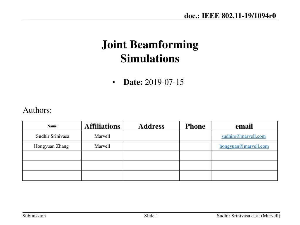
Joint Beamforming Simulations. Date: 2019-07-15. Authors:. Previous submissions [1-4] have looked at different aspects of Joint BF/MU processing “Joint BF” [4] refers to multiple APs jointly steering a single packet with one or more streams to one STA

E N D
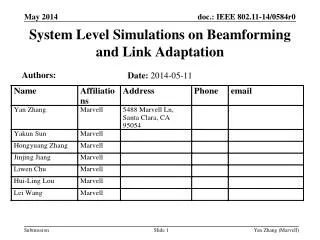
Joint BeamformingSimulations • Date: 2019-07-15 Authors: Sudhir Srinivasa et al (Marvell)
Previous submissions [1-4] have looked at different aspects of Joint BF/MU processing • “Joint BF” [4] refers to multiple APs jointly steering a single packet with one or more streams to one STA • In this submission, we primarily focus on the feasibility of Joint Beamforming with different non-idealities/impairments • Independent CFO across multiple APs. • Carrier Frequency drift in APs between NDP and steered packet. • Timing synchronization between NDP and steered packet for slave APs. • Propagation delay between the APs to the STA • Simulations show even a low CFO impacts the Joint-BF throughput considerably • However, simple schemes like 11ax-midambles can be used in the jointly steered packet to offset the impact of residual CFO Overview Sudhir Srinivasa et al (Marvell)
Trigger packets before NDPA-NDP and DATA can be used for control signaling as well as for synchronization. • Carrier Frequency synchronization • Timing synchronization • Delay estimation • Phase synchronization • (MAC signaling) etc Joint AP Beamfoming Sounding & Feedback (Synchronized transmission) Exchange Beamforming DATA transmission (Synchronized transmission): Sudhir Srinivasa et al (Marvell)
Sounding/NDP • Requires synchronized (both CFO and SFO pre-compensation) transmission for NDP packet. • The master/primary AP sends a trigger packet, and slave APs will synchronize w.r.t the master AP. • During the NDP packet, the slave APs apply CFO & SFO pre-compensation w.r.t master AP. • DATA transmission • The synchronization procedure is similar to sounding packet. • Timing and phase is also synchronized between the sounding and data transmission using the channel estimates of trigger packets at slave APs. NDP & DATA packet transmission Sudhir Srinivasa et al (Marvell)
Two Scenarios: • Case 1: Nss=2 STA • Two APs with 4 antennas each; or Four APs with 2 antennas each • Case 2: Nss=4 STA • Two APs with 4 antennas each; (or Four APs with 2 antennas each) • Only residual timing/frequency offsets between master – slave APs are modeled • Timing offset is modeled as a 10deg ramp across the entire signal BW on the slave AP • For CFO, we consider two separate cases: 20Hz and 50Hz CFO • Feedback considered is the steering matrix • Compression and De-compression are bypassed, i.e., quantization effects are ignored. • 1ms HEW LDPC packet, 4x+3.2 LTF, Independent DNLOS channels across APs Simulation Setup Sudhir Srinivasa et al (Marvell)
HEW, 80 MHz, Nss=2, ‘D’ channel 2AP 4AP • With SNR < 20 dB, throughput of JBF transmission is similar to single AP with 8 transmit antennas. • Significant degradation in peak throughput even with residual CFO of 20 Hz. • Peak throughput degradation higher with higher (50Hz) residual CFO Sudhir Srinivasa et al (Marvell)
The received signal at the nth OFDM symbol of the JBF packet is • The residual CFO realization is different between APs • The CPE seen at the receiver is combination of accumulated CFO from all APs. • STA can correct only for the common phase build-up from multiple APs, i.e., cannot correct for the individual CPE • The effective channel at nth symbol, , is different from the HE-LTF channel estimate () CFO: Phase build-up across symbols Sudhir Srinivasa et al (Marvell)
One solution is to obtain a new channel estimate through midambles. • Midambles can be introduced after every Nth symbol • The STA can use the midambles to update/replace its channel estimate • For example, will be used as channel estimate for the first OFDM symbols. • A midamble is appended after N OFDM symbols, resulting in a new estimate • will be used as the channel estimate for next (N – 1) OFDM symbols, and so on. • Midambles provide new channel estimates with accumulated phase • They reduce the accumulated phase when equalization is done using these new channel estimates. • Note that the BF gain will also degrade as the packet size increases because of the accumulated phase • This is true regardless of whether midambles are present or not. Midamble Sudhir Srinivasa et al (Marvell)
HEW, 80 MHz, Nss=2, ‘D’ channel 2AP 4AP • With midambles: • With residual CFO = 50 Hz: • For SNR < 25 dB, throughput is similar to that of 8x2 single AP • No degradation compared to 8x2 single AP case up to MCS 9. • With residual CFO = 20Hz - No degradation in peak throughput Sudhir Srinivasa et al (Marvell)
HEW, 80 MHz, Nss=4, ‘D’ channel 2AP 4AP • With midambles: • With residual CFO = 50 Hz: • With SNR < 30 dB in 2 AP and < 23 dB in 4 AP configuration, throughput is similar to that of 8x4 single AP. • No degradation compared to 8x4 single AP case up to MCS 9. • No degradation in peak throughput when residual CFO is 20 Hz. Sudhir Srinivasa et al (Marvell)
Even a small residual CFO across APs impacts throughput significantly • Phase buildup from even a low ~20Hz residual CFO causes peak throughput degradation • Midambles help to alleviate the need for very stringent CFO/timing requirements for peak throughput • Midambles help reset the phase buildup caused by residual CFO, and dramatically improve achievable throughput. • CFO/Timing requirements could be more relaxed for mid-range/lower MCSs Inferences Sudhir Srinivasa et al (Marvell)
[1] IEEE 802.11-18/1510, Hongyuan Zhang [2] IEEE 802.11-19/1484 & 0800, Ron Porat, Srinath Puducheri [4] IEEE 802.11-19/0445, Sigurd Schelstraete [5] IEEE 802.11-19/1926r2, Sameer Vermani References Sudhir Srinivasa et al (Marvell)