Download
1 / 15

E N D
SM-781 HWX/PWX Service Manual PWX HWX September 2007 Technical Publications Lexington, KY 40510 www.Clarkmhc.com
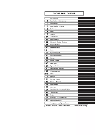
CONTENTS Contents by Group Contents are listed here by Group number : PS PERIODIC SERVICE 12 BATTERY 14 WIRING 16 ELECTRIC MOTORS 17 CONTACTORS 19 MOTOR CONTROLS 20 DRIVE UNIT 23 BRAKE SYSTEM 25 CASTER ASSEMBLY 28 HYDRAULIC SYSTEM 34 LIFT CYLINDERS 35 LIFT LINKAGE and LOAD WHEELS 39 SHEET METAL 40 SPECIFICATIONS SM 781, May '07 CONTENTS-1
Truck Models Covered by this Manual This manual consists of “base” module that pertains to all HWX/PWX models and other modules that pertain only to specific models. Manuals shipped with the truck contain the base module and the mod- ules specific to the purchased truck. You may, however, purchase specific modules and expand your manual to fully cover multiple models. To do so, order the desired modules as you would any other Clark part. Arrangement and Use of this Manual Clark arranges parts and service procedures by stan- dardized Groups. In this manual, Groups are similar to “chapters”. Groups are listed in the indexes on the next page. You can quickly locate a specific point in the manual by using the headers and footers that appear on every Section page. The following illustration points out these areas. Each Group begins with a table of contents that shows the Sections contained within the Group. Lengthy Sections also begin with a table of contents. Each Group and Section has an identifying name and number, or “ID”. Each page also has a unique ID. The page ID con- sists of three numbers separated by hyphens. The three numbers represent the Group number, the Sec- tion number, and the page number. For example, “00-1-2” on the lower corner of the page indicates Group 00, Section 1, page 2. This manual is intended for the use of trained service personnel. Please read Group SA, “Safe Mainte- nance”, and the Operator’s Manual before working on or operating the truck. The Group number sometimes has a letter or letters added to it in parentheses if one or more variations of the Group exist. For example, if the truck has a stan- dard transaxle, Group 06 is expressed as “06(S)”; if the truck has a hydrostatic transmission, Group 06 is expressed as “06(H)”. Copyright Clark Material Handling 2007 SM781, May ’07
GROUP PS PERIODIC SERVICE GROUP PS PERIODIC SERVICE Maintenance Schedule .................................... Section 1 Planned Maintenance Program ...................... Section 2 The PM Inspection Form ................................. Section 3 SM 781, May '07 Group PS PERIODIC SERVICE,
Group PS, Periodic Service Section 1. Maintenance Schedule “Periodic Service” and “Planned Main- tenance” Determining Maintenance Intervals Time intervals on the charts on the next four pages and elsewhere in this manual relate to truck operating hours as recorded on the hourmeter, and are based on experience Clark has found to be convenient and suitable under nor- mal operation. Standard operating condition classifica- tions are: The term “periodic service” includes all maintenance tasks that should be performed on a regularly scheduled basis. The term “Planned Maintenance” indicates a formalized program of basic inspections, adjustments, and lubrica- tions that the Clark service organization provides custom- ers at a prescribed interval, usually 50-250 hours. The recommended basic “Planned Maintenance” procedure is given in Section 2 of this Group. Normal Operation: Eight-hour material handling, mostly in buildings or in clean, open air on clean, paved surfaces. Severe Operation: Prolonged operating hours or constant usage. Extreme Operation: The current Section,”Maintenance Schedules,” specifies all maintenance tasks.including Planned Maintenance tasks.that should be performed periodically, and suggests intervals at which they should be performed. In sandy or dusty locations, such as cement plants, lumber mills, and coal dust or stone crushing sites. High-temperature locations, such as steel mills and foundries. Sudden temperature changes, such as constant trips from buildings into the open air, or in refrigeration plants. If the lift truck is used in severe or extreme operating con- ditions, the maintenance intervals should be shortened accordingly. • • • IMPORTANT MAINTENANCE INTERVALS. If the lift truck is used in severe or extreme operating conditions, the maintenance intervals should be shortened ace. Put upright in vertical posi- tion and fully lower the forks or attachment. SM 781, May ’07 Maintenance Schedule • PS-1-1
Group PS, Periodic Service Section 2. Planned Maintenance Program P.M. CHECK SHEET A special coding system on the P.M. Check Sheet allows truck condition to be reported with a minimum number of words. As the P.M. is performed, a check mark should be made in the appropriate box of the component being checked. Visual Inspection A. Oil leaks √ B. Switches √ C. Drive Tire √ ( √ ) indicates the particular truck component or system has been checked and is O.K. (x) indicates the component or system is in need of a minor adjustment or service (not part of the nor- mal P.M.) that should be taken care of in the near future. (r) indicates there is a potential problem that could result in damage to a component or system and requires attention. (s) indicates the need for urgent repair or replace- ment of a component or system and the truck should be shut down as eminent damage or possi- ble injury may result. The nature of problems found during a PM should be noted in the “comments” portion of the check sheet. Whenever a system or component is faulty or unsafe, it must be noted on the check sheet, and reported to the des- ignated authority at the conclusion of the P.M. ! Remove all jewelry before examining electri- cal components. • D. Load Wheels √ E. Caster Wheels • √ F. Control Linkage Operational Tests A. Brakes √ s • r B. Brake Switch C. Horn √ • D. Steering √ x E. Speed Control F. Lift and Lower Control √ CODE = = = = O.K √ x r s WARNING Adjust(Not P.M) Repair or Replace Requires Shop Repair O.K. Pontential Urgent SM 781, May ’07 Planned Maintenance Program • PS-2-1
Group PS, Periodic Service Visual Inspection 3_ Inspect Pallet Forks for obvious damage • Forks should not be bent or warped. If the forks are damaged, report condition to the designated authority. 1, Inspect Battery Plug & Truck Recelitacle • • Disconnect battery from truck. Inspect the spring loaded connectors in the truck battery receptacle and check the battery plug con- nectors. Severely burned connectors should be noted on the P.M. check sheet. 4. Rider Models • • l Inspect Frame Components l Check truck console, access cover and doors for damage. l Inspect nameplates and decals for damage and to be sure they are not missing. 2, Inspect Battery Cover for damage • • The cover should not be dented. A badly dented Check Cover for Damage cover could short out across the battery cell connectors. The cover should be free to swing open and closed without binding. • PS-2-2 • Planned Maintenance Program SM 781, May ’07
Group PS, Periodic Service 4A. Walkie Models • Look for excessive tire wear, cuts, breaks, chunk- ing or bond failure between the tires and wheels. Note condition on the PM check sheet. Remove embedded objects from the tires. Be sure, wheel fasteners are secure and none are missing. Make certain grease fittings are not damaged or missing. • • Inspect Frame Components Check truck console, access cover and doors for damage. Inspect nameplates and decals for damage and to be sure they m not missing. • • • • 5, Check for obvious oil leaks 7. Expose Internal Components • Make a quick overall inspection for leakage. If an oil leak appears to be major, note condition on the check sheet for immediate attention. Minor leaks should be repaired during the P.M. • Open the access doors exposing the drive unit, brake, lift cylinder, hydraulic unit and SCR control. Each door hangs on a hinge pin. Lift the doors from their pins and set them to one side. 6. Inspect Tires & Wheels • Check for obvious damage to tires on the load, caster and drive wheels. SM 781, May ’07 Planned Maintenance Program • PS-2-3
Group PS, Periodic Service 8. Connect Truck Battery 10. All Models • Connect truck battery and check truck operation. Check the horn to be sure it operates. Operational Tests 11. All Models Check the hour meter to be sure it operates. • 9. All Models • Turn the key switch on. PS-2-4 • Planned Maintenance Program SM 781, May ’07
Group PS, Periodic Service 12. Check Steer Control Handle • If there is binding, hard spots or movement appears to be stiff this indicates either lack of lubrication, misadjusted or damaged steering ring. Report condition on the P.M. check sheet. • • Walkie Models Be certain the control handle is mounted securely at the base of the drive unit. Make sure fasteners are tight and none are none missing. • • 14. Check Brake Oneration • Move the steer control handle downward 10 ° degrees from vertical (brake on) position. Operate truck in reverse at a slow rate of speed. Slowly move control handle upward from the 10 ° travel (brake off) position. As Control Handle annroaches "Brake On" position: • • Rider Models Check the mounting bracket to be sure it is securely mounted to the base of the drive unit. Make sure fasteners are tight and none are missing. • • • 13. Check Steering • Operate truck in reverse at a slow rate of speed. Move control handle through a full right and full left turn. Steering should be smooth without bind- ing or hesitation. 1. The brake switch should operate shutting off the drive motor. 2. The brake should operate bringing the truck to a stop. SM 781, May ’07 Planned Maintenance Program • PS-2-5
Group PS, Periodic Service Operate the truck in forward at a slow rate of speed. Slowly move control handle upward from the 10 ° (brake off) position. The brake should apply when handle reaches the full up (brake on) position. Now, check the brake at a high rate of speed in both forward and reverse directions. 14A. Next, check for proper brake operation by moving the handle downward from the 10 ° (brake off) position. The brake check should be done at Low and High Speeds, and in Forward & Reverse direc- tions. • ! WARNING After checking the coast control, be certain to deactivate this function position before resuming normal truck travel. • • 15. Optional Coast Control (HWX Models) The coast control deactivates the brake and enables the truck to be "jogged" with the travel control and coasted for order picking. • Press the two order picking switches at the same time for 1 sec to activate the coast control function. • Select the Forward switch ON and press one of the order picking switches for 1 sec to deactivate the coast control function. ! Be sure the brake switch should be OFF position during activating the coast control function. CAUTION • If operation is not satisfactory, note condition on the P.M. check sheet. Report condition to desig- nated authority for immediate attention. NOTE Plugging Control is normally used for grad- ual brake applications. Braking with the steer control handle is normally used in emergency situations and parking the truck. 16. Check Travel Speeds Check Acceleration Check High Speed • Drive truck in a straight line, looking in the direc- tion of travel. Listen for any unusual drive train noise. Accelerate from low to high speed. Acceleration should be a smooth transition from creep through • • PS-2-6 • Planned Maintenance Program SM 781, May ’07
Group PS, Periodic Service top speed. If transition is erratic, the accelerator circuit should be checked. • When moving a truck through this type door, pres- sure from the door strips can cause the emergency reversal switch to operate changing the direction of truck travel. By overriding the reversal switch, the truck can pass through the curtain door without miss hap. To simulate the above, operate truck in slow speed reverse. "Depress button to override" and then depress the reversal (belly) switch. Truck travel should remain in slow speed reverse. Note condi- tion on the P.M. check sheet. • 17. Check Hi-Speed Control • • Drive truck forward, in a straight line of travel. Fully rotate Directional Speed Control (1) until maximum (solid state control) speed is obtained Depress Hi-Speed Button (2). This transition should be smooth. If it is not, if it is erratic, jerky etc., the accelerator should be adjusted (Group 19). Note condition on the P.M. check sheet. • 19. Elevate and Lower Pallet Forks • Elevate pallet forks to maximum lift height. As the forks elevate, check to be sure they elevate smoothly and evenly without binding. Lower forks. Look for erratic motion as they lower. They should lower smoothly without hesitation. If there is erratic, jerking motion or binding of linkage as the forks elevate or lower, the lift link- age should be checked and adjusted (Group 35). Note condition on the P.M. check sheet. • • 20. Discharge the Capacitors • • Be sure the battery is unplugged. Discharge capacitors using a 100 ohm, 10 watt resistor connected between the Positive and Nega- tive power terminals on the control. Hold the resis- tor in place for 10 seconds before removing. 18. Override Control • The override control is used to by-pass the emer- gency reversal switch circuit. This is desirable when the truck is operating in areas where plastic strip curtain doors (etc.) are used. Example: • SM 781, May ’07 Planned Maintenance Program • PS-2-7
Thank you very much for your reading. Please Click Here. Then Get COMPLETE MANUAL. NO WAITING NOTE: If there is no response to click on the link above, please download the PDF document first and then click on it.
Group PS, Periodic Service • Check wire harness condition. Check for loose connections and harness damage. Report condition on P.M. check sheet ! CAUTION Using a shorting device without a "resistor load" could cause damage to the control. ! WARNING Discharging the capacitors without using specified resistor could cause serious Injury to yourself and bystanders. ! WARNING Prior to discharging the capacitors, make certain the cover is installed on the control panel power base. 21. HWX Models • • Inspect Operator Grab Rail Check hand rail for security of mounting. Try mov- ing hand rail fore and aft checking for loose con- nections and damage. The mounting bolts should be torqued to lOO- 120 lb. in. Make certain the switch housing is mounted securely and the switches are not damaged. • PS-2-8 • Planned Maintenance Program SM 781, May ’07
Group PS, Periodic Service Section 3 The PM Inspection Form • As an aid to service technicians performing and documenting PM inspections, Clark has prepared an Electric Truck Planned Maintenance Report form. (Sample appears on the next page.) • Use this form as a checklist, and make a record of your inspection and truck condition. Note the spe- cial coding system for indicating the importance of needed repairs and/ or adjustments. SM 781, May ’07 The PM Inspection Form • PS-3-1