Download
1 / 17

E N D
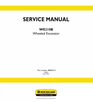
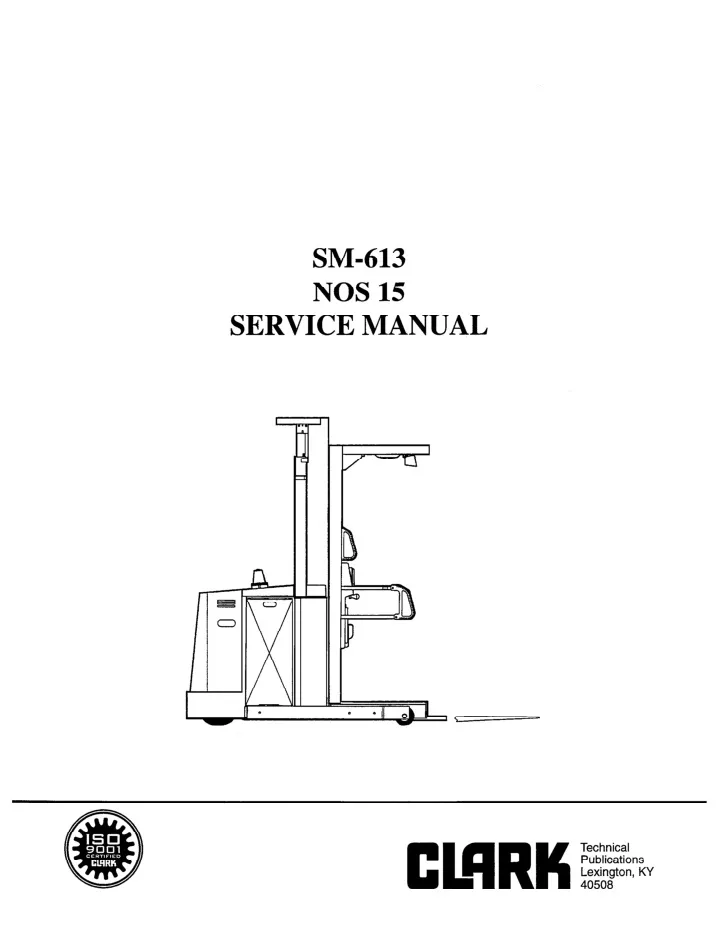
SM-613 NOS 15 SERVICE MANUAL
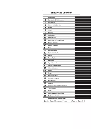
GENERAL INFORMATION (GI) Section 1 Section 2 Section 3 Section 4 Section 5 Pages l-3 Pages l-5 < Pages l-5 Pages l-9 Pages l-4 Introduction & Technical Specifications and Data Maintenance Schedule & Lubrication Chart Paint and Decals & Repair Tools Battery Care and Service Metric to US Chart, Torque Chart, Test Information & Coversion Factors ELECTRIC CONTROL (EC) Section 1 Section 2 Section 3 Section 4 Section 5 Section 6 Pages l-4 Pages l-9 Pages 1-19 Pages 1-61 Pages 1-26 Pages l-8 Basic Electrical Theory Basic Electrical Operation for Curtis PMC Service Guide for PMC Control Electrical Schematic &Wiring Troubleshooting Troubleshooting Do’s and Dont’s & Troubleshooting Flow Charts by Symptom Standard Speed Potentiometer Adjustments for Curtis PMC & Electric LifbLower Control (Logic Unit Adjustment) EV-100 Contactors and Maintenance Pages 1-13 Section 7 Section 8 Pages l-6 HYDRAULIC SYSTEM (HD) Section 1 Section 2 Section 3 Section 4 Section 5 Section 6 Pages l-8 Pages l-5 Pages l-2 Pages 1-3 Pages l-5 Pages l-2 Basics of Hydraulics Basic Hydraulic Operation and Schematic Emergency Platform Lowering Main Hydraulic Lifi Relief Pressure Adjustment Accumulator Charging Gptional Power Steering System Relief Pressure Adjustment DRIVE ASSEMBLY (DA) Section 1 Section 2 Section 3 Section 4 Section 5 Section 6 Pages l-2 Pages l-5 Pages l-6 Pgaes l-11 Pages 1-21 Pages 1-2 Transmission Drive Assembly (General Information) Transmission Drive Assembly (Repair and Service & Installation) Transmission Drive Assembly (Dismantling Lower Section) Transmission Drive Assembly (Assembling Lower Section) G.E. DC Drive Motors Drive Tire BRAKE SYSTEM (BR) Section 1 Section 2 Section 3 Pages l-2 Pages l-4 Pages l-3 Electromagnetic Brake Operation (General Information) Electromagnetic Brake Operation (Maintenance & Adjustments) Electromagnetic Brake Operation (Disassembly and Assembly - Early Version) Electromagnetic Brake Operation (Disassembly and Assembly - Current Version) Section 4 Pages l-3 Page 1 8l95
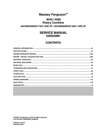
TABLE OF CONTENTS STEERING SYSTEM (ST) Section 1 Section 2 Section 3 Steering System (General Information) Steering System (Maintenance) Steer Cable (Wire Rope) (Replacement and Adjustments) & Reccommended Assembly Steer Cable Adjustments Pages l-5 Pages 1 Pages l-3 Pages l-2 Section 4 LOAD CARRIER (LC) Section 1 Section 2 Section 2 Section 4 Section 5 Pages 1 Pages l-3 Pages l-2 Pages l-2 Pages l-5 Mast Maintenance and Repair (General Information) Mast Maintenance and Repair (Lift Chain and Sheaves) Mast Maintenance and Repair (Roller Bearings) Mast and Platform Removal Mast and Platform Installation BODY AND FRAME (BF) OPTIONAL EQUIPMENT (OE) Page 2 5/95
GENERAL INFORMATION INTRODUCTION NOTICE This manual has been intended to give the trained serviceman procedures to maintain and service NOS 15 Order Selector. Only trained service personnel should perform service and/or repairs to this or any other type of industrial truck. Repair procedures have been worked out for ease of repair and to keep repair times to a minimum. Not following these procedures or taking short cuts could result in damage to other components, longer repair times and/or a possibility of injury. a all factory installed guards, safety devices and/or shields in their secured and proper place. READ THIS MANUAL BEFORE ATTEMPTING TO ADJUST OR SERVICE THIS UNIT! WARNING: Read and observe all warnings on the unit before operating or servicing. Do Not operate this or any other unit without “CLARK Trucks meet all applicable requirements of ANSI B56.1 at time of manufacture. CLARK will not assume any liability for injuries or damages arising from or caused by the removal, disconnection or disengagement of any part from any of it’s trucks. CLARK recommends all replacement parts are of OEM (Original Equipment Manufacturer) origin. Any modifications and/or additions which affect capacity or safe operation of CLARK trucks shall not be performed without CLARK’s prior written approval. A user should consult the Local Authorized Dealer if the user’s intended application is outside the designed performance characteristics of the truck. Dimensions and performance specifications shown may vary due to manufacturing tolerances. Per- formance is based on an average size truck and is affected by weight, condition of the truck, battery, optional equipment and operation area. CLARK products and specifications are subject to change without notice.” GI 1-l
GENERAL INFOlUKATION TECHNICAL SPECIFICATIONS AND DATA NOS 15 SPEEDS I. Loaded 5.0 mph 38 fpm 69 fpm ynloaded 6.0 mph 61 fpm 71 fpm A. Travel B. Lifting 2 Stage C. Lowering II. ELECTRICAL (AMP DRAW @ 24 VOLT) ynloaded 115-155 max 240 to 280 max Loaded 120-160 max 425 to 480 max 45 to 50 max 30-35 max A. Travel B. Main Lift Pump D. Steering at Relief at Travel III. HYDRAULIC 6.3 gallons A. Capacity of Reservoir B. Relief Pressures 1. Main Lift 2. Steering 2550 psi 725 psi Iv. TIRES & WHEELS A. Drive Tire Standard 12 x 4.5 x 8 Poly 13076-16 l.Size 2. Compound 3.Part# . B. Load Wheel 1. Size 2. Compound 3.Part# 6x3 Poly 10761-002 GI l-2 5195
NOS 15 MAINTENANCE SCHEDULE a WARNING: Never operate a damaged or faulty truck. Never smoke when working around truck. Never repair, clean or lubricate any part of truck with battery connected. Never use open flame to check electrolyte level in battery. Never make unauthorized repairs. Time Period Function Daily Check water level in battery. Check oil level transmission. Check all wheels and tires. Remove any and all tape, plastic and material. Check operation of truck steering and speed change including all warning and safety devices (if equipped), horn, speed limit switch, lift limit switches, lights. Ensure that unit lifts and lowers properly. Check electric magnetic brake operation. Check oil levels and insure unit has been greased. Check hydraulic tank with mast (forks) fully lowered. Check for and correct any leaks. 100 Hours weekly Check speed of truck and plugging distance. * * Check brake linkage. Adjust as necessary. Lubricate pivot points. See lubrication chart. Check entire truck for loose items, power and control wires, linkage, nuts and bolts. 5195 GI 2-1
GENERAL INFOR.M.ATION NOS 15 MAINTENANCE SCHEDULE Period Time Function weekly 100 Hours (Cont’d) Clean battery terminals of corrosion. Check electrolyte level. Inspect plugs and battery cables. Check lift chains, heel of fork should not touch the floor with mast completely lowered, adjust as required. Clean and inspect motor brushes. Use only low pressure air or vacuum. Check all hydraulic hoses and fittings for wear or leaks, repair as required. Inspect contact tips. Clean any and all dirt or corrosion from terminal area of PMC Controller units. 30 Days 200 Hours Check steering linkage, cables and chains for proper operation. Make adjustment as needed. * * Lubricate entire truck (see lubrication chart) for type and points. Check safety devices, horn, alarms (if equipped), lift limit switch, slow speed adjustment, loose chain for operation, lanyard (tether) and belt. Repair or adjust before truck goes back into operation. ** ** Measure forks for wear. Check for cracks or damage. 300 Hours 60 Days Check entire truck frame and pivoting points for cracks or worn bearings, repair or replace as needed. Check hydraulic pressure setting, should be 2550 +/- 50 PSI. Inspect brake rotor and pads. Check and adjust platform rollers. Check drive tire and torque bolts to 200 Wlbs. GI 2-2 5195
GENERAL INFORiWATION NOS 15 MAINTENANCE SCHEDULE Time Function Period 60 Days 300 Hours (Cont’d) Clean drive motor and inspect commutator. Use only low pressure air or vacuum. 1000 Hours Yearly Change transmission fluid, requires 3-3/4 pints refill. * * Change hydraulic oil and filter. Check amp draw reading for lift pumps and drive motors. Check lift chain with wear gauge and replace as needed. Check mast uprights and rollers, re-shim or replace as needed. Repair or replace as necessary when inspection finds this part worn or damaged: 1. Drive or hydraulic motor brushes. Springs should be replaced along with brushes, 2. Brake rotor pads. Contact tips. 3. Steering linkage and chains. Should be replaced only, do not repair. 4. 5. Lift chains. Should be replaced as a set only, do not repair. 6. Load wheel. - Always repack bearing whenever a wheel is changed. Remember the largest cause of load wheel failure is material getting caught in wheel. * Trucks operating in freezer, wet or brine conditions must be serviced twice in the standatd maintenance period and special types of lubricants should be used. ** OSHA requires the forks to be measured during Planned Maintenance. The forks must be replaced when the heel of the fork has had its thickness reduced to 90% of its original thickness (10% of the fork has been worn off). Refer to ANSI/AWE B56.1. 5195 GI 2-3
LUBRICATION CHART L- 9- I5 n\ I ” cd95 GI 2-4
GENERAL INFORMATION LUBRICATION CHART me Lubricant of Lub. Points Item No. Description Interval 1 Hydraulic Reservoir Valvoline Super Hydro F32-U Check daily/Drain & clean yearly (Approx. 6 gallon capacity) (1) 2 Hydraulic Reservoir Cap Valvoline Super Hydro F32-U Check 30 days or 200 hours Clean w/solvent and oil (1) 3 Hydraulic Tank Drain Change yearly or 2000 hours (1) 4 Hydraulic Oil Filter Hydraulic Oil Replace during oil change (1) 5 Hydraulic Reservoir Suction Filter Clean during oil change (1) 6 Transmission Oil Plug 80/90 Oil Check daily/Change yearly or 2000 hours (1) 7 Transmissi& Drain Plus Change yearly; 3-314 pints to fdl (1) 8 Transmission Oil Level Oil should not be below this level (1) 9 Lift Chain Heavy SAE Oil Check 30 days or 200 hours 10 Chain Sheave Mob&x #22 Check 2 weeks or 200 hours (2) 11 Load wheels Mobile #22 Check 2 weeks or 200 hours (2) 12 steering Box Mobilux #22 Check yearly or 2000 hours Clean and refill (1). 13 Spmcket, Gear Shaft (Power steering only) Mobile #22 Check 2 weeks or 200 hours (2) Mobile #22 14 Battery, Roller Bearing Check 6 months or 1000 hours Remove/Clean/Repack (8) low oil Pivot Points 15 Lubricate 30 days or 200 hours (6) low oil Steering Chain (2 & 3 Stage Power Steering) Clean and lubricate 16 (2) GI 2-5 a 5195
GENERAL INFORMATION PAINT & DECALS BOTH SIDES OF ’ ARM, BOTH SIDES OF TRUCK GI 3-1
GENERAL INFORMATION PAINT & DECALS 2 STAGE MAST d 2 STAGE I SERIAL w %T HYR RES. - CLARK .I 6 Q 5/95 GI 3-2
GENERAL INFOl2MATION PAINT & DECALS 3 STAGE MAST d 3 STAGE MAST ONLY I Q 22 26 DATA PLATE 8 20 21 8 22 . I w 3 S&i MAST ONLY u GI 33
GENERAL INFO~ATION PAINT & DECALS QE JDESCRIPTION ITEM NO, PART NO, 1 2 3 7 8 9 10 11 12 13 14 15 16 17 18 19 20 21 22 23 24 25 26 30 Caution Pinch Point Label Decal, “Clark” Logo Decal, 24V Only Decal, “Clark” Mast Logo Decal, caution - Polarity Metal Tack Decal, “No Riding” Decal, Warning Forks Decal, Warning - Operator Plate, “Clark” Logo Decal, Flag - USA Decal, Caution Safety Belt Decal, Caution Body Decal, Schematic Nameplate, Serial Number & Capacity Decal, Hydraulic Oil Lift/Lower Plate Forward/Reverse Plate Rivet, Pop Open End Decal, Emergency Lowering Hex Key Decal, Warning Battery Gate Decal, Parking Brake Decal, Emergency Lowering Instructions Paint, Black (Gallon) Paint, Green (Gallon) 97836-lOKOO-Fl 39250-006 39250-004 39250-002 39244-002 39137-002 39204-002 12485-116 39246-000 39250-003 39250-001 39248-000 39242-000 39432-006 AR 1 1 2 1 4 1 AR 1 1 1 1 1 1 1 1 1 1 4 1 1 4 1 1 AR AR * 8977-000 39321-000 39322-000 27607-003 39435-000 41261-031 39409-000 39438-000 3925 l-000 23300-034 23300-035 *Consult Factory with Model and Serial Number. GI 3-4
Thank you very much for your reading. Please Click Here. Then Get COMPLETE MANUAL. NO WAITING NOTE: If there is no response to click on the link above, please download the PDF document first and then click on it.
REPAIR TOOLS Below is a picture of the extraction tool used for removing the pin or socket contacts used in all plug connectors on the NOS 15. This tool is made by Amp Incorporated or can be ordered from CLARK. ENURGED FOR Cl&WY. EXTRAC’llON TIP CAP DJ'WW~ON PART NO. Extraction Tool Pin Socket 458994-l 41271-027 41271-071 For plug connector part numbers see appropriate parts page in the units Parts Manual. Part numbers change according to how many wires they require. 5195 GI 3-5
GENERAL INFOMATION BATTERY CARE AND SERVICE Introduction The motive power industrial battery is the lifeblood of an electric lift truck. The battery supplies energy so that the truck can do productive work. When the battery is charged and maintained in top condition the load gets moved, material stored, paper stacked and rail cars and trailers filled and emptied. The service technician, move man and company president all depend on the electric lift truck for their livelihood. If the battery fails on the job people are out of work, the down time means lost money. The battery for you lift truck represents a sizeable investment. It makes good sense to purchase the correct battery for the job. Taking care of that investment in the best possible way makes even more St?llSe. This text tells how to select the correct battery and how to take care of it. It also explains how that batty works. If you understand the mechanics of something you are better able to take care of it. Some of the material presented in the text is not new. We have gathered information from the people who manufacturer batteries and related equipment. It is presented here to help you, the service technician, understand and take care of batteries. a working near a battery area. WARNING: When working with any battery always wear protective equipment, as in rubber gloves, rubber apron and protective f=e shield. No Smoking at any time when Theory and Construction of Lead-Acid Storage Batteries Storage batteries do no actually store electrical energy. Instead they accept the electrical energy delivered to them during charging periods and convert it into chemical energy. A battery in use is said to be discharging. During discharge the chemical energy in the battery is converted into usable elec- trical energy. Battery Construction The internal construction of a lead-acid industrial motive power battery is similar to that of the com- mon automobile battery. The interior is divided into cells. Each cell contains a set of altemating positive and negative plates called “electrodes” (See Fig. 1) There is always one more negative plate - one on each end. Separators are placed between each plate for insulation and the set is immersed in an electrolyte such as a sulfuric acid solution. An automotive battery has the same type of cells, however industrial cells are much larger and more rugged to give longer lift and increased capacity since their work load is greater. GI 4-l 5/95