Download
1 / 1
10 likes | 122 Views
Modeling the Cardiovascular Inferior Venous System Jim Clear, Chase Houghton, Meghan Murphy Biomedical Engineering, Vanderbilt University, Nashville, TN 37235. OBJECTIVES. RESULTS CONT’D. RESULTS CONT’D. ABSTRACT. RESULTS CONT’D. Achieved Anatomically Representative Heart. Purpose

E N D
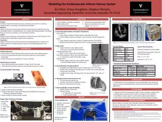
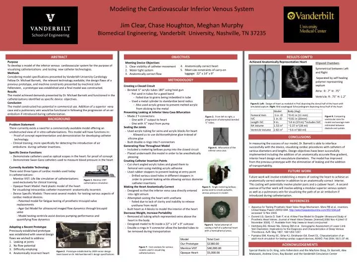
Modeling the Cardiovascular Inferior Venous System Jim Clear, Chase Houghton, Meghan Murphy Biomedical Engineering, Vanderbilt University, Nashville, TN 37235 OBJECTIVES RESULTS CONT’D RESULTS CONT’D ABSTRACT RESULTS CONT’D Achieved Anatomically Representative Heart Purpose To develop a model of the inferior venous cardiovascular system for the purpose of visualizing catheterizations and testing new catheter technologies. Methods Considering model specifications presented by Vanderbilt University Cardiology Fellow Dr. Michael Barnett, the relevant technology available, the design flaws of a previous prototype, and machine constraints presented by machinist John Fellenstein, a prototype was established and a final model was constructed. Results The model achieved demands presented by Dr. Michael Barnett and functioned in the catheterizations identified as specific device objectives. Conclusion The model constructed has potential in commercial use. Addition of a superior vena cava and a pulmonary vein would be functional in following the progression of an air embolism if introduced during catheterization. • 4. Anatomically correct heart • 5. Meet size constraints of carry-on luggage: 22” x 14” x 9” Meeting Device Objectives Clear visibility of catheter movement Water tight system Anatomically correct flow Ellipsoid Chambers Symmetrical between Left and Right Separated by self healing polymer representing septum Atria: R: .7” H: .75” Ventricle: R: .75” H: 1.2” METHODOLOGY Creating a Closed Circuit - Bended ½” acrylic tubes 180° using heat gun - Put sand in tubes for a good bend - Failed due to grains being imbedded in tube - Used a metal cylinder to standardize bend radius - Also used acrylic grease to prevent melted acrylic from sticking to the metal Preventing Leaking at Inferior Vena Cava Bifurcation - Made 2 Y-connectors: - One with 1” output to heart - One with ½” input from pump Sealing the Joints - Used acrylic tubing for veins and acrylic blocks for heart - Allowed us to use dichloroethylene glue instead of silicone glue - Built double o-rings into Y-connectors Generating Flow Throughout Model - Included a metering bellows pump into the closed circuit - Placed underneath the model in order to be anesthetically pleasing Creating Catheter Insertion Points - Cut short angled acrylic tubes and glued them to femoral vein using melding acrylic adhesive - Used rubber stoppers to prevent leaking at entry point - Drilled various sized holes in different stoppers in order to prevent leaking while allowing various diameter catheterinsertions Making the Heart Anatomically Correct - Designed so that the inferior vena cava directly entered into right atrium - Attempted casting the heart with urethane - Failed due to lack of clarity and inability to release urethane from mold - Built heart as 4 blocks to model the interior of the heart Decrease Weight, Increase Portability - Removed all tubing which represented veins above the heart in the body - Designed model to fit inside a 22” x 14” x 9” suitcase - Double o-rings in Y-connector allow the bended tubes to be removed during transportation Figure 8. Left: Design of heart as modeled in ProE depicting the dorsal half of the heart with simulated septum. Right: Mid esophageal Echocardiogram depicting dorsal half of the heart Figure 9. Comparing ventricular sizes for model and average male estimated between diastole and systole. Figure 3. From left to right, a progression of attempted bended ½” tubes. BACKGROUND Problem Statement There currently exists a need for a commercially available model offering an unobstructed view of in vitro catheterizations. This model will have functions in: - Proof of concept experimentation and demonstration for developing catheter technology. - Clinical training, more specifically for detecting the introduction of air embolisms during catheter insertions. Specific Device Functions - Demonstrate catheters used as optical scopesin the heart: for proof of concept - Demonstrate Swan-Ganz catheters used to measure blood pressure in the heart Currently Available Technology There exist three types of cardiac models used today in catheterizations: - Mentice VIST: Life like simulation of catheterizations used exclusively for clinical training. - Opaque Heart Model: Hard plastic model of the heart for visualizing intracardiac catheter movement- anatomically incorrect. - Device Specific Models: There exist several models for testing various aspects of cardiac medical devices. - Patented model for fatigue testing of prosthetic tricuspid valve replacements - Agar Gel Model for ultrasound imaged flow dynamics through bicuspid valve - Model testing ventricle assist devices pumping performance and quantifying flow dynamics Adapting a Recent Prototype Previously established prototype was established with several design flaws we wished to address: Leaking at joints No flow potential Difficulty emptying Anatomically incorrect heart CONCLUSIONS In measuring the success of our model, Dr. Barnett is able to interface successfully with the device, visualizing cardiac procedures with catheters of various diameters and lengths. Design objectives have been successfully implemented including the addition of an anatomically accurate flow gradient, interior heart design and vasculature diameters. The model has improved from the previous prototype with the elimination of leaking and the addition of transportability. Figure 4.Bifurcation of the inferior vena cava. FUTURE WORK Future work will involve establishing a means of casting the heart to achieve an anatomically correct exterior in addition to an anatomically correct interior. This casting will potentially involve plaster paris and a cadaver heart . A second avenue of further work will involve adding a modular superior venous system as well as a pulmonary vein for visualizing the path of an air embolism if introduced during catheterization. Figure 1. Mentice VIST catherization simulation Figure 5. Single metering bellows pump used to create pulsatile, venous pressure in model. REFERENCES • Appartus for Testing Prosthetic Heart Valve Hinge Mechanism. More RB et al., inventors. United States Patent US5531094. http://www.freepatentsonline.com/5531094.pdf accessed 12 Nov 2009. • Durand LG, Garcia D, Sakr F, et al. A New Flow Model for Doppler Ultrasound Study of Prosthetic Heart Valves. Journal of Heart Valve Disease. [Internet] 2006 Nov 4 [cited 12 November 2009]; 17. Available from: http://www.icr-heart.com/journal/. • Hertzberg BS, Kliewer Ma, Delong DM et al. Sonographic Assessment of Lower Limb Vein Diameters: Implications for the Diagnosis and Characterization of Deep Venous Thrombosis. AJR. May 1997; 168:1253-1257. • Pantalos GM, Koenig SC, Gillar KJ, Giridharan GA, Ewert DL. Characterization of an adult mock circulation for testing cardiac support devices. ASAIO. Feb 2004; 50(1):37-46. Figure 6.Failed attempt of casting a half of a spherical heart with a hemispherical press. ACKNOWLEDGEMENTS Figure 7. Cost analysis for various models used in visualizing catheterizations Special thanks to Dr. King, John Fellenstein and the Machine Shop, Dr. Barnett, Alex Makowski, Andrew Cross, Ray Booker and the Vanderbilt Simulation Center Figure 2. Prototype established by 2009 senior design team based on Dr. Michael Barnett’s design specifications