Download

1 / 13
130 likes | 137 Views
Federal Aviation Administration. Measuring Oxygen Concentration in a Fuel Tank Ullage. ISFPWG Meeting Koeln, Germany May 19 - 20, 2009. William Cavage AJP-6320 Fire Safety Team Wm. J. Hughes Technical Center Federal Aviation Administration. Outline. Background

E N D
Federal Aviation Administration Measuring Oxygen Concentration in a Fuel Tank Ullage ISFPWG Meeting Koeln, Germany May 19 - 20, 2009 William CavageAJP-6320 Fire Safety TeamWm. J. Hughes Technical CenterFederal Aviation Administration
Outline • Background • Technologies/Methods Examined • Test Equipment and Procedures • Results • Previous Results • Calibration Gas Exposure • Flight Simulation • Summary
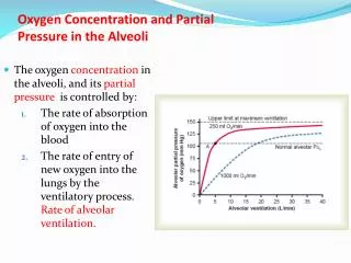
Background • FAA has been seeking to improve fuel tank safety in the wake of TWA Flight 800 in July of 1996 • Rule published requiring extensive flammability reduction on both future built and existing aircraft on present types • The measurement of ullage oxygen concentration is important to the fuel tank inerting community when researching methods, validating models, and certifying systems • FAA method for measuring ullage oxygen concentration at reduced ullage pressures has been successful but can be cumbersome • Emerging products have the potential to simplify and improve upon R&D / Certification work for fuel tank inerting
Technologies/Methods Examined • Improved FAA gas sampling method • Made design changes to OBOAS regulated sample train and packaging based on lessons learned during FAA flight testing • New system is lighter, smaller, quieter, but not proven to have equivalent level of safety • Light Absorption with unregulated gas sample train (Oxigraf) • Unregulated sample train uses a sensor that measures infrared light absorption using a tunable laser diode (TLD technology) • Proprietary software used to interpret spectral data • Optical fluorescence using in situ probe(ASF) • Small fiber optic probe uses spectrometer to interpret coherent light signal which is highly dependent on temperature/pressure • Used in situ (in place) which has many advantages (low power, small size/weight, rapid response) but also has limitations
Light Absorption Method using TLD Oxigraf O2N2 Flight TestOxygen Analyzer
Testing Performed • First – had all methods used in a PVC tube which was flooded with various calibration gases at various temperatures and altitudes • Also examined response time of method by seeing how long it took for instrument to go from 5% to 15% (within 0.1% of stability) • Second - installed the available methods in test tank and exposed them to simulated CWT ullage environment and flight cycle • Used existing 17 cubic foot aluminum fuel tank in altitude chamber • Put fuel in tank as well as inerted the ullage with nitrogen • Performed simulated mission with ground heat up, ascent, cruise, and descent with simulated inerting system performance • Temperature between 110 & -10 ºF, altitudes 0-36K feet
Results – Previously Acquired Data • Previously performed tests illustrated how the optical fluorescence method in situ could follow trends of FAA method with large magnitude errors • Had trouble giving valid numbers at low partial pressures • Also the temperature cycling of the mission seemed to effect the data adversely
Results – Calibration Gas Exposure • Exposed all methods to the stated calibration gases at several altitudes and temperatures typical of a commercial transport airplane fuel tank ullage • Preliminary data with optical fluorescence system did not do well so manufacturer went off to work out the problems • the FAA method and light absorption method duplicated calibration gases well (+/- 0.2% O2 from 5-15% O2) • The light absorption method was the fastest responding method with the FAA method and the optical fluorescence method in a distant second (more than twice as slow) • The optical fluorescence has the potential to be the fastest when developmental software is made more streamlined • FAA method will never be significantly faster
Results – Airplane Fuel Tank Simulation • Measured fuel tank test article ullage [O2] with both the FAA method and the light absorption method • Results of Oxigraf and FAA method very close • The inerting of test tank erratic due to problems, but this illustrates the small advantage of rapid response
Summary • Both the FAA method and the light absorption method duplicate calibration gases well at a variety of conditions and both agree on oxygen concentration measurements made during a simulation of an inert commercial transport airplane fuel tank flight cycle • Light absorption system has faster response time but appears to be of little advantage • Light absorption system already performed some flight testing and is slated for more with several OEMs / Operators • Optical fluorescence method still working out problems but slated for more chamber examinations in May