Download
1 / 13
130 likes | 304 Views
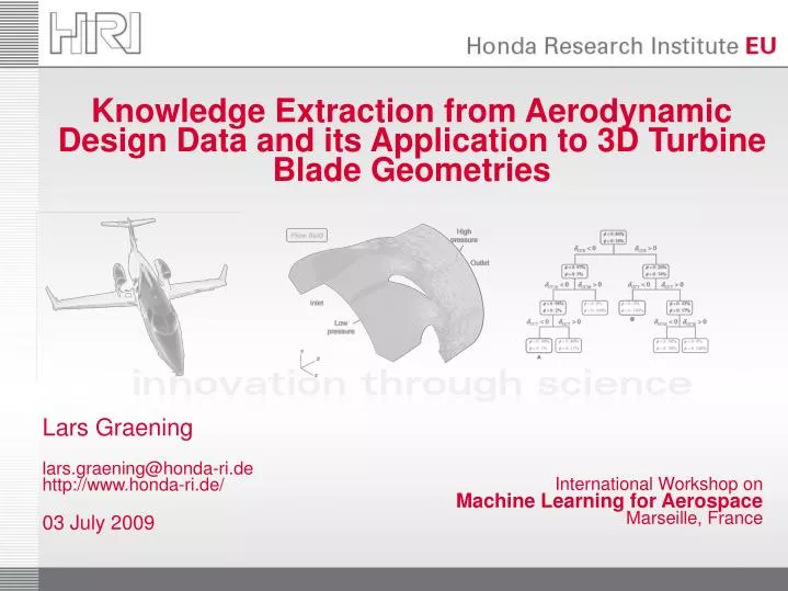
Knowledge Extraction from Aerodynamic Design Data and its Application to 3D Turbine Blade Geometries. International Workshop on Machine Learning for Aerospace Marseille, France. Lars Graening lars.graening@honda-ri.de http://www.honda-ri.de/ 03 July 2009. Outline.

E N D
Knowledge Extraction from Aerodynamic Design Data and its Application to 3D Turbine Blade Geometries International Workshop onMachine Learning for AerospaceMarseille, France Lars Graeninglars.graening@honda-ri.dehttp://www.honda-ri.de/03 July 2009
Outline Universal representation of design modifications Knowledge extraction from unstructured surface meshes Validation of the extracted knowledge
3D Turbine Blade Honda Business Jet Knowledge extraction from a 3D turbine blade design data set Ultra-low aspect ratio transonic turbine stator blade of a small Honda turbofan engine Part of the stator section 3D Blade Design Pressure side Leading edge Suction side Trailing edge
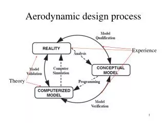
Knowledge Extraction DesignDatabase Design Generation& Modification Evaluation Design data (Design,Performance) • CFD simulation • Wind tunnel • Real physicalenvironment • … • CAD software • Rapid Prototyping • Splines,FFD / DMFFD • … Pre-Processing Optimizer Knowledge (e.g. Design Rules) KnowledgeExtraction • Aerod. Engineer • Computer: • Evo. Opt. • Response Surface • … Usually huge amount of design data is generated during the design and optimization process. How can we extract knowledge from the design data resulting from various optimization runs where different shape representationsare used?
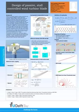
Universal Design Representation & Pre-Processing Universal representation: Vertex A’ Vertex A • Use unstructured surface mesh as a universal geometric representation • Vertices sample the design surface, triangles define the neighborhood, normal vectors define local curvature ModifiedSurface Mesh Displacement ReferenceSurface Mesh Displacement: • Measure of the local deformation along the normal vector of a reference design • Using performance difference instead of performance values • An identification of corresponding vertices is needed The calculation of the displacement leads to a reduction in the number of parameters under consideration
Knowledge Extraction from Aerodynamic Design Data What are the mean differences ofmultiple designs relative to a base design? How similar are two designs? Which design regions are sensitiveto performance changes? Where are unchanged and mostfrequently changed design regions? log
Knowledge Extraction from Aerodynamic Design Data Blade geometries How are distant design areas interrelated? • A reduction of the parameters is needed • Assuming neighboring vertices with similar sensitivity belong to the same design region • Clustering vertices to sensitive design regions • Cluster centers are used to analyze interrelations Design Rules
Design Rules Investigate the consequences of an interrelated displacement of distant vertices to the performance Pressure Side: Suction Side: How reliability is the extracted information? A: A reduction of the blade thickness is expected to increase the performance B: Surprisingly, reducing the thickness at the suction side but increasing the thickness at the pressure side is expected to decrease the performance
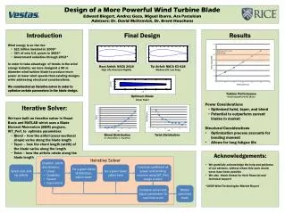
Knowledge Validation Object Point Control Point Algorithm for Knowledge Validation:(using Direct Manipulation of Free Form Deformation) Generate CFD mesh for thereference blade Deform the design usingDirect Manipulation of Free-Form Deformation Displacement • Select vertex and calculate its new position based on the given displacement • Adapt the control points of the control volume concerning the new vertex coordinates • Deform the surface mesh and the CFD grid based on the modifications of the control volume • Perform CFD calculation to calculate the performance of the new blade design Knowledge (e.g. design rule) Apply deformations to theCFD mesh Simulate the flowusing CFD (HSTAR3D) Performance Menzel, S., Olhofer, M., Sendhoff B.: Direct Manipulation of Free Form Deformation in Evolutionary Design Optimization, PPSN 2006
Knowledge Validation • The hypothesis of the direct relation between performance and displacement of CC7 is true • Using DMFFD for validation and utilization works out well Sensitivity Surface Deformation CC7 The displacement of vertex CC7 is positivecorrelated with the aerodynamic pressure loss of the turbine blade! Resulting Blade Performance after CFD(Pressure Loss) CFD Grid Deformation worse better Reference blade
Knowledge Validation A: Decrease in pressure loss of about -10.50 % The performed experiments confirm the expected outcome of the extracted hypothesis B: Increase in pressure lossof about 5.86 %
Summary & Outlook • framework for extracting knowledge from aerodynamic design data • technique based on DMFFD for validating the extracted knowledge • validation experiments provide evidence for the reliability of the knowledge extraction techniques • outlook measurements are needed that allow to extract rules which are potentially interesting for the aero engineer