Download
1 / 50
510 likes | 523 Views
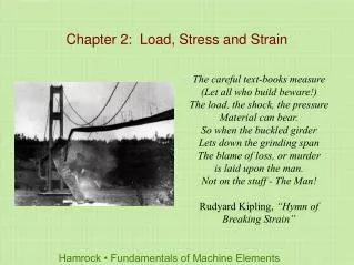
Chapter 7 Transformations of Stress and Strain. Introduction. Previously we were calculating stresses about specified areas that pass through a point. Here, we will consider the most general state of stress at a given point.

E N D
Chapter 7 Transformations of Stress and Strain
Introduction Previously we were calculating stresses about specified areas that pass through a point. Here, we will consider the most general state of stress at a given point. The linear strain in the top surface of the bar is being measured by a strain gage. This part is concerned with how the components of stress are transformed under a rotation of the coordinate axes
Introduction The most general state of stress at a point may be represented by 6 components, Normal Shear Same state of stress is represented by a different set of components if axes are rotated. Normal Shear
Plane Stress Plane Stress - state of stress in which two faces of the cubic element are free of stress. For the illustrated example, the state of stress is defined by Examples: A thin plate subjected to forces acting in the midplane of the plate. The free surface (not subjected to an external force) of a structural element or machine component.
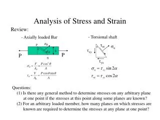
Transformation of Plane Stress Assume that a state of stress exists at point Q (with σz=τyz=τzx=0) defined by the stress components Determine the stress state associated with the same element after it has been rotated through an angle about the z axis (hence σz’=τy’z’=τz’x’=0)
Transformation of Plane Stress To determine the normal stress σx’ and the shearing stress τx’y’, we consider the equilibrium conditions of a prismatic element with faces perpendicular to the x, y, and x’axes.
Transformation of Plane Stress Solving the equations yields Using The expression for the normal stress σy’ is obtained by replacing θ by θ+90o
Principal Stresses The previous equations are combined to yield parametric equations for a circle, Circle of center (σave,0) and radius R
Principal Stresses Point A: corresponds to the maximum value of σx’ and zero τx’y’ Point B: corresponds to the minimum value of σx’ and zero τx’y’ Principal stresses occur on the principal planes of stress with zero shearing stresses.
Shearing Stress Maximum shearing stress occurs for θp and θs are 45o apart Maximum shearing stress
Example 1 7-2: For the given state of stress, determine the normal and shearing stresses exerted on the oblique face of the shaded triangular element shown. Use a method of analysis based on the equilibrium of that element, as was done in the derivations of Sec. 7.2.
Example 2 7-6: For the given state of stress, determine (a) the principal planes, (b) the principal stresses
Example 3 7-12: For the given state of stress, determine (a) the orientation of the planes of maximum in-plane shearing stress, (b) the maximum in-plane shearing stress, (c) the corresponding normal stress
Example 4 7-22: Two members of uniform cross section 50 × 80 mm are glued together along plane a-a, that forms an angle of 25o with the horizontal. Knowing that the allowable stresses for the glued joint are σ = 800 kPa and τ = 600 kPa, determine the largest centric load P that can be applied
Example 5 7-25: A mechanic uses a crowfoot wrench to loosen a bolt at E. Knowing that the mechanic applies a vertical 100 N force at A, determine the principal stresses and the maximum shearing stress at point H located as shown on top of the 18 mm diameter shaft.
Example 6 7-26: The steel pipe AB has a 102 mm outer diameter and a 6 mm wall thickness. Knowing that the arm CD is rigidly attached to the pipe, determine the principal stresses and the maximum shearing stress at point K.
Mohr’s Circle for Plane Stress The circle can be used to calculate the stress state of an element at any orientation. For a known state of plane stress σx, σy and τxy, plot the points X and Y and construct the circle centered at C. The principal stresses are obtained at A and B. The direction of rotation of Ox to Oa is the same as CX to CA.
Mohr’s Circle for Plane Stress With Mohr’s circle uniquely defined, the state of stress at other axes orientations may be depicted. For the state of stress at an angle θ (cw) with respect to the xy axes, construct a new diameter X’Y’ at an angle 2θ (cw) with respect to XY. Normal and shear stresses are obtained from the coordinates X’Y’.
Mohr’s Circle for Plane Stress Mohr’s circle: Centric axial loading Points D and E yield the orientation of the planes of maximum shearing stress
Mohr’s Circle for Plane Stress Mohr’s circle: Torsional loading Points A and B define the principle planes and yield the principle stresses
Example 7 7-36: For the given state of stress, determine using Mohr’s circle the normal and shearing stresses after the element shown has been rotated through (a) 25o clockwise, (b) 10o counterclockwise.
Example 8 7-44: Two members of uniform cross section 50 × 80 mm are glued together along plane a-a, that forms an angle of 25o with the horizontal. Knowing that the allowable stresses for the glued joint are σ = 800 kPa and τ = 600 kPa, determine the largest centric load P that can be applied using Mohr’s circle.
Example 9 7-55: Determine the principal planes and the principal stresses for the state of plane stress resulting from the superposition of the two states of stress shown.
General State of Stress Consider the general 3D state of stress at a point and the transformation of stress associated with element rotation. Our analysis will be limited to the determination of σn on a plane of arbitrary orientation. State of stress at Q defined by:
General State of Stress Consider the tetrahedron with a face perpendicular to the line QN with direction cosines The forces exerted on ABC consist of a normal force σn ΔA directed along QN and of a shearing force of magnitude τΔA perpendicular to QN
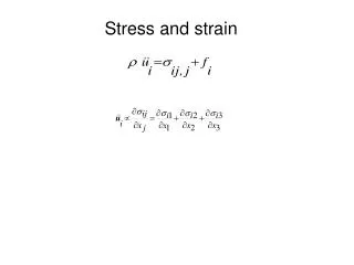
General State of Stress The statics requirements lead to Dividing by ΔA and solving for σn
General State of Stress Now select the axes in such a way that the right-hand member reduces to the three terms containing the squares of the direction cosines The coordinate axes a, b, c are referred to as the principal axes of stress. The corresponding coordinate planes are known as the principal planes of stress and the corresponding normal stresses σa, σb, and σc as the principal stresses at Q.
Mohr’s Circle 3D Analysis of Stress Circle AB rotation about the principle axis Qc Circle BC rotation about the principle axis Qa Circle AC rotation about the principle axis Qb The transformation about any different axis will lead to a stress state defined by a point in the shaded area.
Mohr’s Circle 3D Analysis of Stress The three circles represent the normal and shearing stresses for rotation around each principal axis. Radius of the largest circle yields the maximum shearing stress.
Mohr’s Circle 3D Analysis of Stress Plane stress case: the z axis is a principal Points A and B (representing the principal planes) are on opposite sides of the origin O. Case I: • The corresponding principal stresses are the maximum and minimum normal stresses for the element • The maximum shearing stress for the element is equal to the maximum “in-plane” shearing stress • The planes of maximum shearing stress are at 45o to the principal planes.
Mohr’s Circle 3D Plane stress case: the z axis is a principal • The planes of maximum shearing stress correspond to points D and E, and are at 45o to the principal planes.
Mohr’s Circle 3D Analysis of Stress Plane stress case: the z axis is a principal Points A and B (representing the principal planes) are on the same sides of the origin O. Case II: • The circle defining σmax, σmin, and τmax for the element is not the circle corresponding to transformations within the plane of stress • The maximum shearing stress for the element is equal to half of the maximum stress • The planes of maximum shearing stress are at 45o to the plane of maximum normal stress
Mohr’s Circle 3D Plane stress case: the z axis is a principal • The normalsQd’ and Qe’ to the planes of maximum shearing stress are obtained by a 45o rotation about the Qb axis of the Qa or the Qc axis.
Example 10 7-68: For the state of stress shown, determine the maximum shearing stress when (a)σy = 40 MPa, (b)σy = 120 MPa. (Hint consider both in-plane and out-of-plane shearing stresses.)
Example 11 7-71: For the state of stress shown, determine the maximum shearing stress when (a) σz = 0 MPa, (b)σz = 60 MPa, (c)σz = -60 MPa.
Example 12 7-75: For the state of stress shown, determine the value of τxy for which the maximum shearing stress is (a) 63 MPa, (b) 84 MPa.
Example 13 7-79: For the state of stress shown, determine two values of σy for which the maximum shearing stress is 80 MPa.