Download
1 / 55
610 likes | 905 Views
IEEE 802.11 Wireless LAN Part I Introduction, Physical layer, basic MAC. Why Wireless Networking?. Mobility Enable users to physically move while using an appliance. Cost Saving Easy to install in difficult-to-wire areas (E.g., a historical Museum building)

E N D
IEEE 802.11 Wireless LANPart IIntroduction, Physical layer, basic MAC
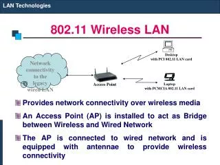
Why Wireless Networking? • Mobility • Enable users to physically move while using an appliance. • Cost Saving • Easy to install in difficult-to-wire areas (E.g., a historical Museum building) • Quick to set up (no need to pull cables) • Increased reliability due to less used cables (the probability of cable down time thus becomes less) • Get rid of messy cables in office, home, and other places.
Wireless Signal Property • Two type of antennas: • Omni-directional • Directional
Signal Propagation and Quality Is Often Unpredictable • A small change in position or direction may result in dramatic differences in signal strength -- whether a station is stationary or mobile!
Wireless LAN Usages Ad hoc mode Infrastructure mode
IEEE 802.11 Equipments Lucent’s Orinoco (formly Wavelan) PCMCIA card Lucent’s USB interface card Lucent’s access point Lucent’s Orinoco PCI card
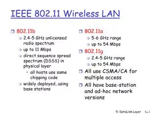
Physical Technology • Three physical technologies are defined and used in IEEE 802.11: • Direct-sequence spread spectrum • Can support 1, 2, 5.5 and 11 Mbps bandwidth • The most popular one in the current market. • Frequency-hopping spread spectrum • Can support only 1 and 2 Mbps bandwidth • Popular once but now seldom used. • Infrared light (diffused or point-to-point) • Can support up to 16 Mbps bandwidth • Rarely used.
Why Direct Sequence Scheme? • Spread a signal’s power over a wider band of frequencies. • Thus this scheme requires higher bandwidth to transmit data signal. • Because most interference noise signal is typically narrow in bandwidth, • This will result in much less interference and bit errors.
Frequency Hopping SS • Must hop to another channel in 400 ms. • Sender and receiver must use the same frequency hopping sequence to correctly receive data. • Good for military purpose because now eavesdropping becomes hard and signal jamming also becomes hard. Each channel uses 1 MHZ spectrum.
Direct Sequence SS • Convert a data signal to a higher data rate bit sequence (referred to as a chipping code). • The code used in 802.11 is a 11-bit Barker sequence 10110111000.
802.11 Uses Unlicensed ISM Band Microwaves also use this area. So your 802.11 transfer may be interfered by your microwave! Nowadays most 802.11 NICs use this area.
Modulation Techniques • DQPSK modulation is used when the transmission rate is 2 Mbps.
DSSS Physical Layer Frame Format MAC Frame • The physical layer header (23 bytes) and the MAC layer header(34 bytes) together cause a lot of overhead. • The SYNC field consists of alternating 0s and 1s. That is, 010101010101 …. A receiver will begin to synchronize with the incoming signal after detecting the sync.
DSSS Physical Layer Frame Format • Start frame delimiter: always 1111001110100000. • Signal: identifies the type of modulation that the receiver must use to demodulate the signal. The value of this field is equal to the data rate divided by 100 Kbps. • In 802.11, a sender can send its frame at either 1, 2, 5.5, or 11 Mbps rate. • To enable the receiver to receive frames that are sent at different rates, the sender always sends the PLCP preamble and header at the fixed 1 Mbps and the receive always listens for frames at 1 Mbps. • Thus the receiver can correctly decode the signal field at 1 Mbps and then switch to a different and higher rate to receive MPDU. • Service: always 0. • Length: define the number of microsecond to transmit the MPDU.
Lucent Orinoco(WaveLAN) Spec. Although you have 11 channels to choose from, selected channels should be separated at least by 30 MHZ to avoid interference. So, actually there are only 3 non-overlapping channels! 11 Mbps 5.5 Mbps 2 Mbps 1 Mbps
Application 1 No access point is needed. PC can communicate easily and directly among themselves. But no QoS can be achieved.
Application 2 Access points are needed. But now Information on wired networks can be accessed and the coverage area is larger. Also QoS now is possible Although two PCs are in the same cell and can communicate directly, their communication still needs to go through the access point.
Application 2 (cont.) If these access points are on the same subnet, when a mobile node move from one cell into another cell, its IP address need not be changed. Otherwise, its IP address needs to be changed and either DHCP or Mobile-IP is needed.
Application 2 (cont.) f1 f1 f1 f1 f2 f1 If these access points use the same frequency channel, when a mobile node move from one cell into another cell, its used frequency channel need not be changed. However, it packet transmission or reception may be interfered by neighboring access points when it is at the cell boundary.
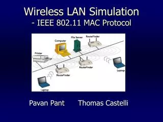
Application 3 Wireless local bridges can be used to wirelessly connect two remote wired networks (e.g., two buildings). The range of these bridges can be up to 30 miles.
Application 4 Wireless relay nodes can act as routers to wirelessly forward packets. (This type of network is called “packet radio network.”) Some big cities in US have deployed this type of networks.
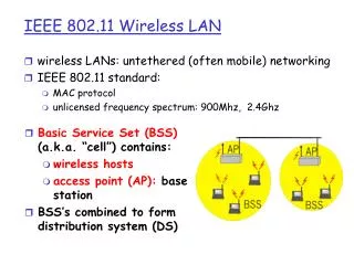
Components of the IEEE 802.11 Architecture • Basic service set: the basic building block of an 802.11 LAN. • Independent BSS: Also called “ad hoc network”. Stations in the same IBSS can communicate directly with each other. • Infrastructure BSS: a station in the BSS needs to become an access point. All other stations need to send packets to the AP, which then forwards the packet to the destination station.
Distribution System • To extend the coverage area of a wireless network, sometimes we want to connect multiple BSSs. • The component used to interconnect BSSs is called “distribution system (DS).” • The medium used for the DS can be different from the wireless medium. (Normally most vendors just use Ethernet as the DS.) • The DS can be considered as a layer-2 network. • An access point (AP) is a station that provides access to the DS by providing DS services in addition to acting as a station. • Data move between a BSS and the DS via an AP.
Extended Service Set • A network that is formed by BSSs and DS is called the “extended service set.” • ESS network appears the same to an LLC layer as an IBSS network. • Stations within an ESS may communicate and mobile stations may move from one BSS to another transparently to LLC. • (So, basically, an extended service set is a layer-2 network.)
Wired and Wireless Networks Integration • A portal is the logical point at which packets from a non-802.11 LAN (e.g., 802.3 Ethernet) enter the 802.11 DS. • It is possible for one device to offer both the functions of an AP and a portal. (E.g., if the DS itself is implemented from 802.2 Ethernet). • Nowadays, what most people say “access point” actually is a portal. This is because access points in today’s markets all connect to an Ethernet.
802.11 Architecture Services • Station services • Authentication • Deauthentication • Privacy (WEP: wired equivalent privacy) • MSDU delivery • Distribution system services • Association (always initiated by the station, not AP) • Disassociation (can be initiated by either AP or station) • Distribution • Integration • Reassociation (always initiated by the station, not AP)
Frame Types • Class 1 Frames • Control Frames • Request to send (RTS) • Clear to send (CTS) • Acknowledgement (ACK) • Contention-Free (CF) • Management Frames • Probe request/response • Beacon • Authentication • Deauthentication • Announcement traffic indication message (ATIM) • Data Frame
Frame Types (cont.) • Class 2 Frames • Management frames • Association request/response • Reassociation request/response • Disassociation • Class 3 Frames • Data frames • Management frames • Deauthentication • Control Frames • Power save poll
Other fields in the Frame Control Field • To DS: set to 1 if the frame is destined for the DS. (I.e., the frame is from a 802.11 station to a host on an Ethernet) • From DS: set to 1 if this frame is from the DS. (I.e., the frame is from a host on an Ethernet to a 802.11 station)
Other fields in the Frame Control Field • More fragment: set to 1 if another fragment of the same frame will follow in a subsequent frame. • Retry: set to 1 if this frame is a retransmission of an earlier frame. • Power management : set to 1 to indicate that this station will be in a sleep mode. • More data: If a station has additional frames to send to a station that is in sleep mode, then the sending station will place 1 in this field. • WEP: set to 1 to indicate that the frame body has been encrypted using the WEP algorithm. • Order: set to 1 to indicate the receiving station that frames must be processed in order.
The Duration Field • The unit of duration is microsecond. This field can be used by RTS/CTS/DATA frames to reserve the wireless channel for a period of time.
802.11 Address Types • Destination address (DA): The final destination address of the MAC service data unit (MSDU). • Source address (SA): The address of the MAC entity that initiated the MSDU transmission. • Receiver address (RA): The address of the access point that is to receive the frame next. • Transmitter address (TA): The address of the immediate preceding access point sending the frame. • BSSID: This is the ID of a BSS. In an infrastructure BSS, this is the MAC address of the station in the access point. In an IBSS, this is a locally administered address formed from a random number. • An address filed may contain DA, SA, RA, TA, BSSID.
The Sequence Control Field • Sequence number is used to detect duplicate frames. (There is a per-source cache (address 2, seq#, frag#) for each source station.) • A frame can be fragmented into several fragments to reduce the frame-error-rate that it may experience over lossy wireless links. • The fragment threshold is a parameter and can be configured.
MAC Architecture • DCF is a distributed contention scheme. (called CSMA/CA, every station must support it.) • PCF is a centralized polling scheme. (Optional. Actually no access points currently support it.)
DCF Provides Priority Data Frame • When the medium becomes idle, Because DCF asks different types of frames to wait a different amount of time before they can be sent to the medium, DCF can provide three priority levels for different types of frames. PCF Frame Control Frame (e.g., RTS/CTS/ACK)
DCF Basic Access Method • If a station wants to send a frame and the medium is currently busy, the station should defer its transmission until the medium becomes idle.
DCF Basic Access Method • Then it should wait a period of time equal to DIFS. • If during this DIFS time the medium is idle, then the station should start a backoff timer. • Otherwise, the DIFS timer should be canceled and later restarted when the medium again becomes idle. • When the station’s backoff timer expires, the station then can send its frame onto the medium. • But, the backoff timer should be suspended whenever the medium is busy.
Backoff Procedure When the medium becomes idle, resume the backoff timer only after DIFS idle time. Suspend the backoff timers if a transfer is going on.
ACK Procedure Retransmit timer expires here • 802.11 performs a link-level ACK scheme. Depending on frame sizes, a frame can be retransmitted up to 4 or 7 times. • If the ACK is not received within a certain time but a valid frame is received, the data transmission is deemed failed. However the received valid frame can be processed.
Exponential Backoff The CW will be exponentially increased for successive failed transmissions. CW will be reset to CWmin immediately after a successful transmission, or the number of retransmission has exceeded a certain value.