Download
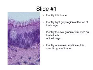
1 / 19
190 likes | 266 Views
Project: IEEE P802.15 Working Group for Wireless Personal Area Networks (WPANs) Submission Title: [ Bit Order Comment Resolution ] Date Submitted: [ “13 July, 2010” ]

E N D
Project: IEEE P802.15 Working Group for Wireless Personal Area Networks (WPANs) Submission Title: [Bit Order Comment Resolution] Date Submitted: [ “13 July, 2010”] Source: [Daniel Popa], Company [Itron, Inc], Address [76 Avenue Pierre Brossolette, 92240 Malakoff, France], E-Mail:[daniel.popa@itron.com] [J.L.Taylor], Company [DTC (UK)], Address [UK], E-Mail:[larry.taylor@discretetime.com] Re: [LB51 Comment Resolution] Abstract: [This contribution proposes a resolution to bit order representation for the 4g amendment] Purpose: [LB#51 Comment Resolution] Notice: This document has been prepared to assist the IEEE P802.15. It is offered as a basis for discussion and is not binding on the contributing individual(s) or organization(s). The material in this document is subject to change in form and content after further study. The contributor(s) reserve(s) the right to add, amend or withdraw material contained herein. Release: The contributor acknowledges and accepts that this contribution becomes the property of IEEE and may be made publicly available by P802.15. Daniel Popa (Itron), Larry Taylor (DTC(UK)) Slide 1 Slide 1
Bit Order Comment Group Related Comments Popa / Taylor 781, 783, 789, 815, 871, 889, 915, 938, 951, 952, 954, 1059-1063 Daniel Popa (Itron), Larry Taylor (DTC(UK))
Additional Changes Additional changes might be required, as a function of the work-in-progress on comment resolution These changes will be only related to eventual reorganization of the structure of PHY components Daniel Popa (Itron), Larry Taylor (DTC(UK))
Text Changes to Draft • General comment • Section 6.3.x introduces the Preamble, SHR and PHR structures and describes each of them for each PHY variant • 6.3.1 refers to 6.3.4a for the preamble for OFDM • 6.3.2 declares exceptions for the SFD for SUN PHYs. It describes the SFD for MR-FSK and MR-O-QPSK but says nothing about the SFD for OFDM • 6.3.3 describes the PHY header for MR-FSK and MR-O-QPSK but not for OFDM • Would it not be easier to read and more consistent with the complete text to treat each PHY separately and define the SHR and PHR just for one PHY in each part of the document? • i.e. have 6.12a.x define the SHR and PHR for MR-FSK, 6.12b.x define the SHR and PHR for MR-O-QPSK and 6.12c.x define the SHR and PHR for OFDM Daniel Popa (Itron), Larry Taylor (DTC(UK))
How it will be ? Section 6.3 General Description of a 4g PPDU; defines bit order rules for PPDU global components: SHR, PHR and PSDU. SHR & PHR Description for MR-O-QPSK SHR & PHR Description for OFDM SHR & PHR Description for MR-FSK Add a dedicated subsection (Section 6.12b.1) to describe mapping between the bit string and fields of the MR-O-QPSK (SHR + PHR) components Add a dedicated subsection (Section 6.12a.1) to describe mapping between the bit string and fields of the MR-FSK (SHR + PHR) components Add a dedicated subsection (Section 6.12c.1) to describe mapping between the bit string and fields of the OFDM (SHR + PHR) components Daniel Popa (Itron), Larry Taylor (DTC(UK))
If not, and we have to keep the complex logic of the existing draft 6.3 • The text change to 6.3 has been defined • In section 6.3.2a change • The Packet Control field is 5 bits in length and is shown in Figure 27a. • to • The Packet Control field occupies the first 5 bits of the PHR as shown in Figure 27a. • Identify the Packet Control field in the replacement PHR diagram as in the following slides • Question – is it useful to retain the naming of the 5 bits as a field instead of just defining the meaning of each group of bits? Daniel Popa (Itron), Larry Taylor (DTC(UK))
Change to 6.2.3b • Change • The Packet Control field of the MR-O-QPSK PHY is five bits in length and is shown in Figure 27b • To • The Packet Control field occupies the first 5 bits of the PHR as shown in Figure 27b • Identify the Packet Control field in the replacement PHR diagram in the following slides • Question – is it useful to retain the naming of the 5 bits as a field instead of just defining the meaning of each group of bits? Daniel Popa (Itron), Larry Taylor (DTC(UK))
Text change to 6.3.3 • Change • The Frame Length field is 7 bits in length and specifies the total number of octets contained in the PSDU (i.e., PHY payload). For the MR-FSK, OFDM, and MR-O-QPSK PHYs, the Frame Length field is 11 bits in length. The Frame Length field is a value between 0 and aMaxPHYPacketSize (see 6.4). For the MR-FSK PHY, the most-significant bit (leftmost) shall be transmitted first. • To • The Frame Length field is 7 bits in length and specifies the total number of octets contained in the PSDU (i.e., PHY payload). For the MR-FSK, OFDM, and MR-O-QPSK PHYs, the Frame Length field is 11 bits in length as shown in figures 27a, 27b and 27f respectively. The Frame Length field is a value between 0 and aMaxPHYPacketSize (see 6.4). Daniel Popa (Itron), Larry Taylor (DTC(UK))
Text changes to 6.3.3a • Change • The Mode Switch Parameter Entry subfield is 2 bits in length… • To • The Mode Switch Parameter Entry sub-field is an unsigned 2-bit integer…(refer to table defining the values) • The Modulation Scheme bits indicate the modulation scheme (see 6.1.2.5a) • To • If phyCurrentPage = 7 Modulation Scheme is an unsigned 2-bit integer identifying the modulation scheme as in Table 3b, otherwise it is not used. Daniel Popa (Itron), Larry Taylor (DTC(UK))
Text changes to 6.3.4a.3 • Change • The PHY header fields include: • — An unsigned 5-bit integer Rate field which specifies the data rate of the payload frame (insert reference to definition of rate values – couldn’t find this) • — One reserved bit after the Rate field • — An 11-bit unsigned integer Frame Length field which specifies the number of octets in the payload • — Two reserved bits after the Frame Length field • — A 2-bit Scrambler seed field (insert reference to where the scrambler seed is defined – couldn’t find this) • — One reserved bit after the Scrambler field • — An 8-bit Header Check Sequence (HCS) CRC taken over the data fields only (insert reference to where the bit correspondence for the HCS is defined – I couldn’t find this) • — Six tail bits, each set to zero, for Viterbi decoder flushing Daniel Popa (Itron), Larry Taylor (DTC(UK))
Changes to 6.12c.4.1 • Delete the following text after Table 75q as it is redundant with 6.3 and now updated: • Each bit in the (SHR,PHR) shall be processed in octet-wise order, beginning with the Preamble field and ending with the last octet of the PHR. Within each octet, the LSB, b0, is processed first and the MSB, b7, is processed last. Daniel Popa (Itron), Larry Taylor (DTC(UK))
Text Change Suggestion - Update the 3rd paragraph of 6.3 to say: Delete “When the transmission order differs from this convention, it is described in the appropriate sub-clause” at the end of the 1st paragraph of 6.3 Change 3rd paragraph in 6.3 as follows “In general, a PPDU packet consists of the following basic components: A synchronization header (SHR), which allows…. A PHY header (PHR), which contains.. A variable length payload (PSDU), which carries… Insert after the last bullet of the 3rd paragraph of 6.3 For SUN PHYs (MR-FSK, MR-O-QPSK and OFDM) the SHR, PHR and PSDU components are treated as bit strings of length n, numbered b0 on the left and bn-1 on the right. When transmitted, they are processed b0 first to bn-1 last without regard to their content or structure as shown in Figure xx. (Note that since the PHR defines the PSDU length in octets, the PSDU bits are numbered b0 to b8*Frame Length-1 ) Note: Changes are in bold italics “In general..” is added since the MSF PPDU has no PSDU Bit order processing at transmitter/receiver Figure xx: Example of bit order processing for a 4g PHY component; the number of octets {m = (k+1)} forming a PHY component is not necessarily an integer value. Daniel Popa (Itron), Larry Taylor (DTC(UK)) Slide 12 Slide 12
Mapping between bit string and PHR fields:4g MR-FSK PHYAll multi-bit fields are unsigned integers and shall be processed MSB first • Delete 1st sentence of 6.3.2a as it is already defined in figure 26a • Replace figure 27a with the following MS = Mode Switching RFU = Reserved for further use FCS = FCS length DW = Data Whitening Figure 27a: MR-FSK PHR component Daniel Popa (Itron), Larry Taylor (DTC(UK)) Slide 13 Slide 13
Mapping between bit string and MSF fields 4g MR-FSK PHYAll multi-bit fields are unsigned integers and shall be processed MSB first • Replace figure 27c with the following MS = Mode Switching MSPE = mode Switch Parameter Entry FEC = new mode FEC field Page = 0 if Channel Page =7 or 1 if Channel Page=8 Mod – Modulation Scheme Md = Mode B = BCH PC = Parity Check Figure 27c: MR-FSK Mode Switching Frame PHR component Daniel Popa (Itron), Larry Taylor (DTC(UK)) Slide 14 Slide 14
Mapping between bit string and PHR fields 4g MR-O-QPSK PHY All multi-bit fields are unsigned integers and shall be processed MSB first • Delete 1st sentence in 6.3.2b • Replace figure 27b with the following PC = Parity Check RM = Rate Mode RFU = Reserved for further use Figure 27b: MR-O-QPSK PHR component Daniel Popa (Itron), Larry Taylor (DTC(UK)) Slide 15 Slide 15
Mapping between bit string and PHR fields 4g OFDM PHY All multi-bit fields are unsigned integers and shall be processed MSB first • Replace figure 27f with the following RFU = Reserved for further use S = Scrambler HCS = Header Check Sequence Figure 27f: OFDM PHR component Daniel Popa (Itron), Larry Taylor (DTC(UK)) Slide 16 Slide 16
Resolutions Daniel Popa (Itron), Larry Taylor (DTC(UK))
Resolutions Daniel Popa (Itron), Larry Taylor (DTC(UK))
Resolutions Daniel Popa (Itron), Larry Taylor (DTC(UK))