Download
1 / 14
140 likes | 413 Views
LECTURE 4: MEASURING MEMBRANE CONDUCTANCE AND CAPACITANCE & VOLTAGE-CLAMP RECORDING. REQUIRED READING: Kandel text, Chapters 8, 9 (beginning), pgs 140-153. We have talked about the properties of solid-state RC electrical circuits.

E N D
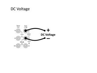
LECTURE 4: MEASURING MEMBRANE CONDUCTANCE AND CAPACITANCE & VOLTAGE-CLAMP RECORDING REQUIRED READING: Kandel text, Chapters 8, 9 (beginning), pgs 140-153 We have talked about the properties of solid-state RC electrical circuits. We have also learned that the resting membrane consists of electrical components: The membrane is a capacitor Channels create ion-specific conductances Concentration gradients establish ion-specific battery potentials We show here that a cell at rest exposed to a transition in transmembrane voltage responds as a simple RC circuit SO LONG AS THE VOLTAGE CHANGES DO NOT ALTER THE OPEN/CLOSED STATES OF ANY MEMBRANE CHANNELS !!!
SWITCH CLOSED t = 0 sec IA + RA VBat - IC IB RB C In an RC electrical circuit, we can measure the resistance (conductance) and capacitance of components by analyzing currents and component voltages induced by applying a voltage step. IA = 10 mV 0 time IC IA IA C= QC / VC = QC (RA + RB) /10 mVRB IA=10 mV/(RA + RB) 0 time 0 time WHEN RA<<< RB IA=10mV/RB AND C = QC / 10mV
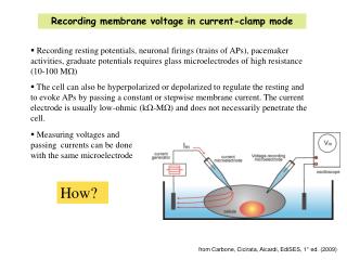
K+ K+ K+ K+ K+ K+ K+ K+ AT STEADY STATE: Na+ IK = - INa out Na+ IK = 22 pA gK = 2 nS RK = 0.5 GW + EK = - 82 mV - in GRAPHIC AND CIRCUIT REPRESENTATIONS OF ION FLOWS ACROSS THE MEMBRANE AT THE RESTING POTENTIAL + + + + + + + + + + + + + + + + + + out Vm = - 71 mV - - - - - - - - - - - - - - - - - - in ENa = + 85 mV EK = - 82 mV out gNa = 0.14 nS out + + + INa = - 22 pA RNa = 7.1 GW Vm = -71 mV - - - - in ENa = + 85 mV + in EK + IKRK= Vm = ENa + INaRNa -82 mV + (22 pA)(0.5 GW) = -71 mV = +85 mV + (-22 pA)(7.1 GW)
K+ K+ K+ K+ K+ K+ K+ K+ AT STEADY STATE: Na+ IK = - INa out out + + + Vm Na+ = -71 mV Ileak = 0 pA gleak = 2.14 nS - - - in Rleak = 0.48 GW + Erest = - 71 mV - in GRAPHIC AND CIRCUIT REPRESENTATIONS OF ION FLOWS ACROSS THE MEMBRANE AT THE RESTING POTENTIAL + + + + + + + + + + + + + + + + + + out Vm = - 71 mV - - - - - - - - - - - - - - - - - - in ENa = + 85 mV EK = - 82 mV Erest + IleakRleak= Vm -71 mV + (0 pA)(0.48 GW) = -71 mV
+ - + - VOLTAGE STEP, TOTAL CHANNEL CONDUCTANCE, AND LEAK CURRENT OBEY OHM’S LAW Ileak For simplicity, we can combine all of the channels and gradients contributing to resting potential into one circuit containing: a resting potential battery Erest and the total conductance of all channels gtotal slope = gleak Vcommand Erest out Ileak gleak Vcommand Cmem Erest (Vcommand - Erest ) x gleak = Ileak in
out out out out gNa = 0.14 nS gNa = 0.14 nS out + + + INa = - 22 pA INa = -20.6 pA Vm = RNa = 7.1 GW RNa = 7.1 GW IK = 42 pA IK = 22 pA gK = 2 nS gK = 2 nS - - - -71 mV - - in RK = 0.5 GW RK = 0.5 GW ENa = + 85 mV ENa = + 85 mV + + + + EK = - 82 mV EK = - 82 mV - - in in in in A VOLTAGE CHANGE ACROSS THE MEMBRANE ACTS INDEPENDENTLY ON EACH COMPONENT OF THE MEMBRANE CIRCUIT + - - 61 mV IMPOSE COMMAND VOLTAGE 10 mV ABOVE RESTING POTENTIAL out + + Vm = - - + - -61 mV in - 61 mV
out out gNa = 0.14 nS INa = -20.6 pA RNa = 7.1 GW IK = 42 pA gK = 2 nS - RK = 0.5 GW ENa = + 85 mV out + + + Vm = + - - + - EK = - 82 mV -61 mV - in in in - 61 mV VOLTAGE STEP FROM RESTING POTENTIAL INDUCES CAPACITANCE TRANSIENT CURRENT AND STEADY-STATE LEAK CURRENT DV VOLTAGE STEP 10 mV TOTAL CHANNEL CONDUCTANCE gtotal(leak) 2.14 nS NET STEADY STATE CURRENT FLOW Ileak 21.4 pA DISCHARGE = 10 mV x C IC x x ITOTAL g = = Ileak = (Vcommand - Vrest ) x gtotal(leak) I 0 0 time
IC ITOTAL Ileak = (Vcommand - Erest ) / Rmem 0 0 time EFFECT OF VOLTAGE STEP ON CURRENTS AND VOLTAGE AT A DIFFERENT SITE WITHIN NEURON SITE OF COMMAND DIFFERENT SITE out + Vcom - Erest Rmem Cmem Rmem Cmem - Raxial in IC ITOTAL Ileak = (Vcommand - Erest )/ 0 (Rmem + Raxial ) 0 time If Raxial is significant, Ileak and voltage divergence from Erest at different site is less and voltage divergence is delayed by Raxial x C time constant
DETERMINANTS OF AXIAL RESISTANCE Raxial ~Distanceaxial/Areacross-sectional Cell soma has relatively large diameter (3 - 30 microns) and cross-sectional area, so Raxial in soma is negligible. Therefore, transmembrane voltage will always be the same at all points around the soma, even during rapid current/voltage changes. Raxial is significant along the axon and thin dendrites. The narrower an axon’s diameter, the larger is Raxial, and the greater delay and attenuation of a voltage change occuring at a distance within the cell.
+ + - - + - THE IDEAL VOLTAGE CLAMP Voltage clamp is the ability to rapidly and stably fix a voltage difference between 2 points. When used in conjunction with a whole-cell patch, voltage clamp allows for the immediate and stable shift in the voltage across the cell membrane. Voltage clamp allows for the measurement of passive membrane properties (leak conductance and membrane capacitance) along with voltage- and time-dependent changes in ion-specific conductances The ideal voltage clamp can be simulated as a “command” voltage battery connected to an on/off switch + - Vclamp out Rleak bath (grounded) Cmem patch pipet Vclamp Erest in CELL
+ - THE REAL VOLTAGE CLAMP A real voltage clamp consists of a feedback amplifier which continuously compares the voltage across the membrane to a command voltage, and injects sufficient current into the cell to make this voltage difference = 0 ground SIMPLIFIED SCHEMATIC OF A TRANSISTOR AMPLIFIER Vcommand POWER SOURCE Iinject VB ground Vmembrane B C A IC Iinject CURRENT MONITOR VA Imem IC~VB-VA bath (grounded) patch pipet Icap If any changes occur in membrane channels causing new currents and drift of Vm, the voltage clamp very rapidly senses this drift and adjusts current injection to maintain Vm = Vcommand CELL
REAL VOLTAGE CLAMP ANALOGOUS TO “WATER LEVEL CONTROLLER” IN LEAKY TUB Inside of tub (inside cell) has width and depth (capacitance) and has an open drain (leak conductance, gleak). Baseline water level (resting potential, Vrest) is set by water level (resting battery, Erest) outside the tub. The water level controller (voltage clamp) measures water level in tub (Vmembrane) and compares it to an adjustable water level set value (Vcommand) and then injects or sucks water from the tub (current injection) with a pressure proportional to the difference in levels (Vcommand - Vmembrane). When a new water level command is applied, the system first injects/sucks a large amount of water to reset water level (Iinject = IC) and then continues to inject/suck smaller amount of water to compensate for water passing through drain and thereby maintains command level (Iinject = Ileak). The flow of water through drain obeys “Ohm’s law”, determined by how much command level differs from resting level and by size of drain. Ileak = (Vcommand - Erest) x gleak
Next Lecture: ION CHANNELS: STRUCTURES AND FUNCTIONS REQUIRED READING: Kandel text, Chapters 6,9