Download
1 / 17
170 likes | 174 Views
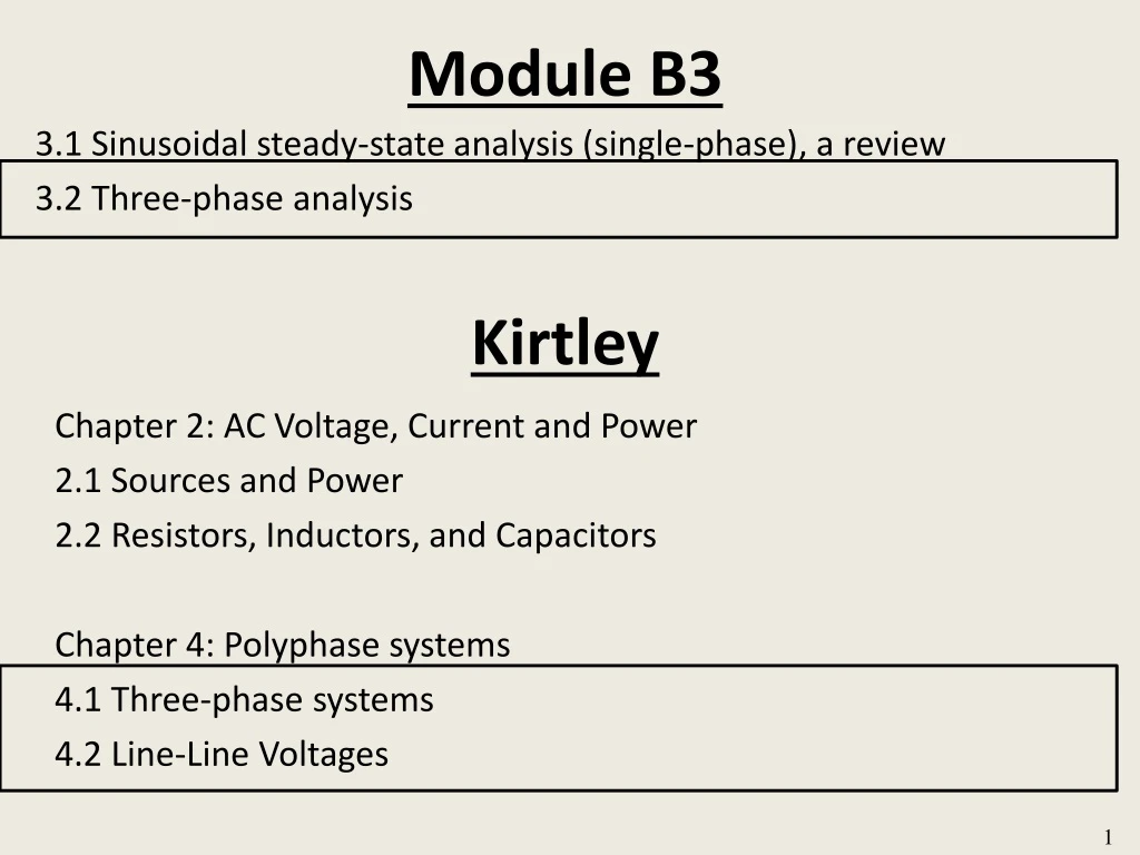
Module B3. Kirtley. Chapter 2: AC Voltage, Current and Power 2.1 Sources and Power 2.2 Resistors, Inductors, and Capacitors Chapter 4: Polyphase systems 4.1 Three-phase systems 4.2 Line-Line Voltages. 3.1 Sinusoidal steady-state analysis (single-phase), a review 3.2 Three-phase analysis.

E N D
Module B3 Kirtley Chapter 2: AC Voltage, Current and Power 2.1 Sources and Power 2.2 Resistors, Inductors, and Capacitors Chapter 4: Polyphase systems 4.1 Three-phase systems 4.2 Line-Line Voltages 3.1 Sinusoidal steady-state analysis (single-phase), a review 3.2 Three-phase analysis 1
Three-phase power All of what we have done in the previous slides is for “single phase” circuits. However, almost all transmission systems in the US are 3-phase AC systems (the only exceptions are a few DC transmission lines). Three-phase AC is preferred over single-phase AC because the investment and operating costs per MW of transmission capacity are more attractive, and because a 3-phase system provides constant power (not pulsating as we saw before) You can see this in the next slide. 2
Three single phase systems? Or one three-phase system? Three-phase power 1 node 3 nodes 3
Three-phase power AC generators on the grid supply 3-phase power. A circuit diagram for the stator of a typical 3-phase generator is provided in the next two slides. 4
a Line-to-neutral (phase) voltages b b a n n c c The identified voltages are referred to as “line-to-neutral voltages,” or “phase voltages.” 5
a Line-to-line (line) voltages b b a n n c c The identified voltages are referred to as “line-to-line voltages,” or just “line voltages.” 6
Rotation Phasor diagram for line-neutral (phase) voltages 120° 120° 120° What is rotating? The peak value of the sinusoid; this peak value is projected onto the positive vertical axis to obtain the instantaneous value of the quantity, a concept equivalent to writing van(t)=Vpeaksinωt. www.animations.physics.unsw.edu.au/jw/phasor-addition.html 7
Rotation Phasor diagram for line-line (line) voltages 120° 120° 120° 8
a Relating phase and line voltages b b a n n c c 9
Rotation Relating phase and line voltages 10
Wye-connected sources and loads b b a n n c c 11
Balanced 3-phase conditions have: • Line and phase voltages related as in previous slides. • Za=Zb=Zc • This results in: Balanced conditions Note: In Wye-connected loads, the line current and the phase current (current through Za) are identical. a b b a n n c c 12
Under balanced conditions, we may perform single-phase analysis on a “lifted-out” a-phase and neutral circuit, as shown below. Per-phase analysis a b b a n n c c 13 13
Per-phase analysis a n Now it is clear that: Also, we still have: 14
Per-phase analysis a n After we perform the single-phase analysis, we may then compute the 3-phase quantities according to: 15
The previous power relations utilize line-to-neutral voltages and line currents. Power may also be computed using line voltages, as developed in what follows: Three phase power relations Likewise, we may develop that 16
In summary: Three phase power relations Note 1: In Wye-connections, the power factor angle θ is the angle by which the line-to-neutral voltage leads the phase current . It is not the angle by which the line-to-line voltage leads the phase current. More generally, the power factor angle at two terminals is the angle by which the voltage across those terminals leads the current into the positive terminal. Note 2: You may see notation VL or VLL for Vab. 17