Download
1 / 22
250 likes | 305 Views
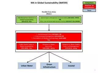
Department of Hydro Sciences, Institute for Urban Water Management. 0 Global water aspects 1 Introduction to urban water management 2 Basics for systems description 3 Water transport 4 Matter transport 5 Introduction to water supply 6 Water extraction 7 Water purification

E N D
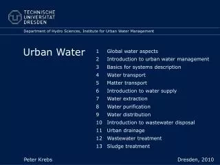
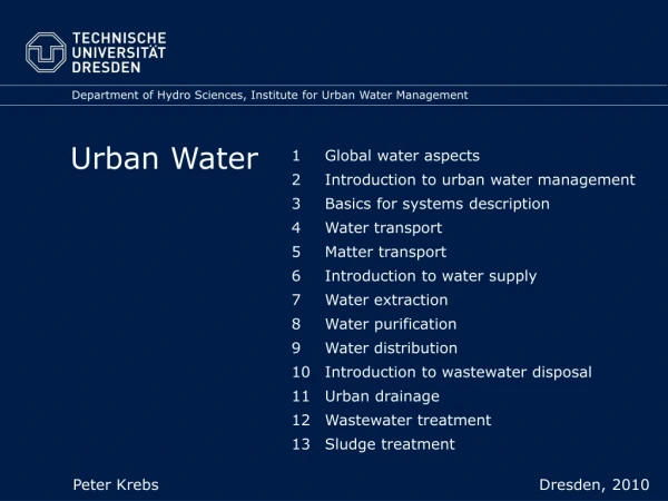
Department of Hydro Sciences, Institute for Urban Water Management 0 Global water aspects 1 Introduction to urban water management 2 Basics for systems description 3 Water transport 4 Matter transport 5 Introduction to water supply 6 Water extraction 7 Water purification 8 Water distribution 9 Introduction to wastewater disposal 10 Urban drainage 11 Wastewater treatment 12 Sludge treatment Urban Water Peter Krebs Dresden, 2010
Peter Krebs Department of Hydro Sciences, Institute for Urban Water Management Urban Water 8 Water distribution 8.1 Systems structure 8.2 Water transport 8.3 Water storage
Peter Krebs Department of Hydro Sciences, Institute for Urban Water Management Urban Water 8 Water distribution 8.1 Systems structure 8.2 Water transport 8.3 Water storage
Network structure Costs Residence time Supply safety Redundant capacity Branched network Low Only in end pipes high, uni-directional flow Low, since only one way to tap limited, large diameters for fire fighting Circular arrangement Only in end pipes high medium, two ways to tap Increased safety for fire fighting water availability Medium Meshed network In parts long, depending on operating conditions high; break-downs only locally effective High safety for fire fighting water availability, higher pressure loss High
HB HB HB Storage arrangement Central Counter Flow through Supply safety good good low Friction loss Low Low, if 2-side supply high Pressure variation Low High Medium Pipes diameters Small Medium High Storage renewal Ev. not good Ev. not good Good Control effort High High Low Flow direction Altering Altering Uni-directional Implementation Flat topography Dep. on topography economic
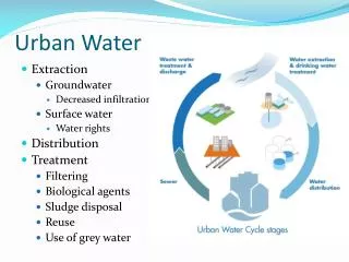
Pumping station High supply region Purification plant Clean water storage tank Reservoir Pressure reduction valve Compensation tank Raw water pumping station Low supply region Pressure increase station Dam Purification plant River Pumping station Clean water storage tank Example of a supply region
Peter Krebs Department of Hydro Sciences, Institute for Urban Water Management Urban Water 8 Water distribution 8.1 Systems structure 8.2 Water transport 8.3 Water storage
Pressure zones Pressure zone 4 Pressure zone 3 Valve 3-4 Pumping station 4 Pressure zone 2 Valve 2-3 Pumping station 3 Pressure zone 1 Minimum pressure Ground floor 2,0 bar per floor +0,5 bar minimum +0,35 bar Valve 1-2 Water treatment Pumping station 1 and 2
Pressure lines Little consumption high consumption Little consumption High consumption Pressure 4 - 10 bar 40 -100 m Supply from reservoir or pump
Little consumption Pressure lines High consumption Pump not operating 40 -100 m Supply from reservoir and pump
Little pressure „No pressure“ 10 -20 m Insufficient pressure
Peter Krebs Department of Hydro Sciences, Institute for Urban Water Management Urban Water 8 Water distribution 8.1 Systems structure 8.2 Water transport 8.3 Water storage
Purposes of storage tanks • Compensation of variations in consumption, covering of peaks • Compensation between pre and main pumping • Control pressure ranges according to respective zones • Safety for supply during operation disturbances • Water for fire fighting (ev. separate pipes) • Could serve as mixing or sedimentation tank • Storage over limited time hygienic store energy
Provide hygienic conditions • protection from pollution • Filtration of air • Temperature constant • No light (growth of algae) • circulation and renewal of water (no regions with high residence time or stagnation) • Smooth surface • Pressure installations for cleaning
Reservoir volume Compensation - between pumping and consumption - usually based on diurnal variations Safety - bridging breakdown and breakages - depending on systems size and structure Fire fighting - depending on systems size and structure - depending on potential damage
Typical values for reservoir volume Compensation 50% of average daily consumption Safety plus fire 50% of average daily consumption fighting Decrease large city supply areas with multiple independent inputs Increase small supply areas with single input Rule of thumb 0,2 to 0,5 m3/person
14 12 (%) 24 10 Q / h Q 8 6 4 rel. use 2 0 0 2 4 6 8 10 12 14 16 18 20 22 24 Time (h) Reservoir dimensioning (i) Diurnal consumption variation and pumping strategies
100 Use 90 0 h - 24 h 80 20 h - 6 h 70 6 h - 16 h 60 rel. consumption and pumping (%) 50 40 30 20 10 0 0 2 4 6 8 10 12 14 16 18 20 22 24 Time (h) Reservoir dimensioning (ii) Diurnal consumption variation and pumping strategies; accumulated
- 5,2 - 18,5 24,7 70,5 44 Resulting storage volumes Option 1 Option 2 Option 3 Pumping from…to 0 – 24 Uhr 20 – 6 Uhr 6 – 16 Uhr 19,5 52 33,5 Max. surplus |S| (%) Max. deficit |D| (%) - 10,5 Compensation volume C = |S| + |D|(%)
Fire fighting • Fire brigade • Insurance companies • Minimum 100 m3 • For multiple independent inputs it can be reduced or even neglected • Need of fire brigade: • Depending on characteristics of area • 0,01 to 0,06 m3/s • 100 m3 provide this for app. 0,5 h to 2,5 h
Water tower (i) Minimum app. 40 m above supply area Large diameters small losses low tower High water depth statics distinct pressure variations higher tower Up to a volume of 200 m3 for one chamber
overflow inlet Lift Daily variation effluent Fire fighting Fire fighting Lift Staircase Effluent Emptying Fire fighting Inlet Cables Overflow Water tower (ii)