Download
1 / 29
290 likes | 293 Views
第 5 章 太陽電池 MATLAB 模擬. Program 1: 太陽能電池之輸出電壓、電流、功率響應 Program 2: The output response of buck converter with load variation Program 3: Solar cell with Buck converter. Program 1 太陽的日照強度 =1 kW/m2 時,且溫度 25 度 C , 當 t=0~3000, 負載 R=R1=6,

E N D
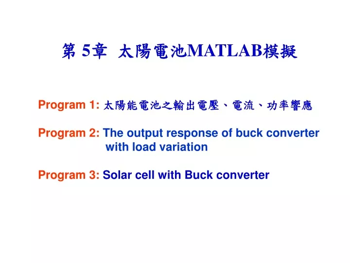
第 5章 太陽電池MATLAB模擬 Program 1: 太陽能電池之輸出電壓、電流、功率響應 Program 2: The output response of buck converter with load variation Program 3: Solar cell with Buck converter
Program 1 太陽的日照強度=1 kW/m2時,且溫度25度C , 當t=0~3000, 負載R=R1=6, 當t=30000~7000, 負載 R=R2=7, 當t=7000~10000, 負載R=R3=8。 畫出太陽能電池之: 輸出電壓響應圖(Fig.1), 輸出電流響應圖(Fig.2) , 輸出功率響應圖(Fig.3) 。
MATLAM Program (Photovoltaicwithload1) %太陽的日照強度=1 kW/m2)時,且溫度25度C ,(t=0~3000, 負載R=R1=6), (t=30000~7000, R=R2=7), (t=7000~10000, R=R3=8) %太陽能電池之輸出電壓響應圖(Fig.1),輸出電流響應圖(Fig.2), 輸出功率響應圖(Fig.3) clear; clc; %參數調整% np = 5; %並聯個數 ns = 10; %串聯個數 k = 1.38*(10^-23); %波茲曼常數 q = 1.63*(10^-19); %一個電子所含之電荷量 T = 298; %太陽能表面溫度 Tr = 298; %參考溫度 A =1.8; %太陽能板理想因數 Irr = 0.3*(10^-19); %逆向飽和電流 Eg = 1.1; %半導體能量間隙所需之能量 Isc = 0.66; %太陽能板在參考溫度和1kW/m^2的日照條件下的短路電流值 Ki = 1.33; %太陽能板短路電流的溫度係數 Si = 1.0; %日到強度 1 dv=0.01; t1=3000; t2=7000;
R1=6; R2=7; R3=8; V(1) =18; Iph = (Isc+Ki*(T-Tr)/1000)*Si; %公式(3) Isat = Irr*((T/Tr)^3)*exp(q*Eg*((1/Tr)-(1/T))/(k*A)); %公式(2) for t=1:10000 if t<t1 R=R1; else if t<t2 R=R2; else R=R3; end end I(t) = np*Iph-np*Isat*exp(((q*V(t))/(k*A*T*ns))-1); %公式(1) IL(t)=V(t)/R; if IL(t)<I(t) V(t+1)=V(t)+dv; else if IL(t)>I(t) V(t+1)=V(t)-dv; else V(t+1)=V(t); end end P(t) = V(t)*I(t); %公式(4) end
%電壓響應圖% t = 1:10000; figure(1) plot(t,V(t),'-b') legend('V(t)',1) xlabel('t') ylabel('V (volt)') hold on %電流響應圖% figure(2) plot(t,I(t),'-r',t,IL(t),'-b') legend('I(t)','IL(t)',1) xlabel('t') ylabel('I(amp)') hold on %功率響應圖% figure(3) plot(t,P(t),'-r') legend('P(t)',1) xlabel('t') ylabel('P(W)') hold on
Program 2 The output response of buck converter with load variation 當t=0~0.03s, 負載R=R1=1, 當t=0.03s~0.07s, R=R2=2, 當t=0.07s~0.1s, R=R1=1。 Plot: diode voltage Vd and output voltage Vo of buck converter from 0s to 0.1s (Fig. 1) diode voltage Vd and output voltage Vo of buck converter from 0.029s to 0.035s (Fig. 2) diode voltage Vd and output voltage Vo of buck converter from 0.069s to 0.075s (Fig. 3) inductor current IL from of buck converter from 0s to 0.1s (Fig. 4) inductor current IL from of buck converter from 0.029s to 0.035s (Fig. 5) inductor current IL from of buck converter from 0.069s to 0.075s (Fig. 6)
MATLAM Program (Buckconverterwithloadvariation2) %The output response of buck converter with load variation % (t=0~0.03s, 負載R=R1=1), (t=0.03s~0.07s, R=R2=2), (t=0.07s~0.1s, R=R1=1) % Plot diode voltage Vd and output voltage Vo of buck converter from 0s to 0.1s (Fig. 1) % Plot diode voltage Vd and output voltage Vo of buck converter from 0.029s to 0.035s (Fig. 2) % Plot diode voltage Vd and output voltage Vo of buck converter from 0.069s to 0.075s (Fig. 3) % Plot inductor current IL from of buck converter from 0s to 0.1s (Fig. 4) % Plot inductor current IL from of buck converter from 0.029s to 0.035s (Fig. 5) % Plot inductor current IL from of buck converter from 0.069s to 0.075s (Fig. 6) clear all; clc; %***Set duty cycle*** d=0.75;%Duty cycle d** T=0.000005; % T=0.000005 N1=200; % N1=200 N2=100; % N2=100, % PWM period Tw=N2*T=0.0005s, % PWM frequency Fw=1/Tw=2kHz % Total simulation time=N1*Tw=200*0.0005s=0.1s,
NL1=60; % Time for load in=NL1*Tw=60*0.0005s=0.03s NL2=140; % Time for load out=NL2*Tw=140*0.0005s=0.07s N2d=d*N2; R1=1; R2=2; L=0.005; C=0.001; Vr=20.; %Input voltage of Buck converter IL(1)=0; %*Initail inductor current Vo(1)=0; %Initial output voltage Vi(1)=Vr; %***Calculate output voltage and inductor current*** for i=1:N1 if i<NL1 R=R1; else if i<=NL2 R=R2; else R=R1; end end
for j=1:N2 k=(i-1)*N2+j+1; % k from 2 to N1*N2+1 if j<=N2d %***During Q1 on*** Vi(k)=Vr; IL(k)=IL(k-1)-T*Vo(k-1)/L+T*Vi(k)/L; Vo(k)=1/(1+T/R/C)*(Vo(k-1)+T*IL(k)/C); end if j>N2d %***During Q1 off*** Vi(k)=0.0; IL(k)=IL(k-1)-T*Vo(k-1)/L+T*Vi(k)/L; Vo(k)=1/(1+T/R/C)*(Vo(k-1)+T*IL(k)/C); end end end
%***Plot output voltage and inductor current*** k=1:N1*N2; figure(1) %subplot(3,1,1) %Plot diode voltage Vi and output voltage Vo from 0s to 0.1s plot(k*T,Vi(k),'-b',k*T,Vo(k),'-r') axis([0.0,0.1,-2,25]); legend(4,'Vd','Vo') ylabel('V') xlabel('s') figure(2) %subplot(3,1,2) %Plot diode voltage Vi and output voltage Vo from 0.029s to 0.035s plot(k*T,Vi(k),'-b',k*T,Vo(k),'-r') axis([0.029,0.05,-2,25]); legend(4,'Vd','Vo') ylabel('V') xlabel('s') figure(3) %subplot(3,1,3) %Plot diode voltage Vi and output voltage Vo from 0.069s to 0.075s plot(k*T,Vi(k),'-b',k*T,Vo(k),'-r') axis([0.069,0.1,-2,25]); legend(4,'Vd','Vo') ylabel('V') xlabel('s')
figure(4) %subplot(3,1,1) %Plot inductor current IL from 0s to 0.1s plot(k*T,IL(k),'-b') axis([0.0,0.1,-2,20]); legend('IL') ylabel('A') xlabel('s') figure(5) %subplot(3,1,2) %Plot inductor current IL from 0.029s to 0.045s plot(k*T,IL(k),'-b') axis([0.029,0.05,-2,20]); legend('IL') ylabel('A') xlabel('s') figure(6) %subplot(3,1,3) %Plot inductor current IL from 0.069s to 0.085s plot(k*T,IL(k),'-b') axis([0.069,0.1,-2,20]); legend('IL') ylabel('A') xlabel('s')
Program 3 Solar cell with Buck converter Duty cycle of buck converter: t=1~2000, duty cycle=0.8 t=2000~4000, duty cycle=0.81 t=4000~6000, duty cycle=0.82 t=6000~8000, duty cycle=0.83 t=8000~10000, duty cycle=0.84 t=10000~12000, duty cycle=0.85 Plot: Solar output voltage V(t) and Buck converter output voltage Vo(t)---Fig. 1 Solar output current I(t) and Buck converter output current Io(t)---Fig. 2 Solar or Buck converter output power P(t)---Fig. 3
MATLAM Program (Photovoltaicwithbuckconverter3) %Solar cell with Buck converter %Duty cycle of buck converter: t=1~2000, duty cycle=0.8 % t=2000~4000, duty cycle=0.81 % t=4000~6000, duty cycle=0.82 % t=6000~8000, duty cycle=0.83 % t=8000~10000, duty cycle=0.84 % t=10000~12000, duty cycle=0.85 %Solar output voltage V(t) and Buck converter output voltage Vo(t)---Fig. 1 %Solar output current I(t) and Buck converter output current Io(t)---Fig. 2 %Solar or Buck converter output power P(t)---Fig. 3 clear; clc; %參數調整% np = 5; %並聯個數 ns = 10; %串聯個數 k = 1.38*(10^-23); %波茲曼常數 q = 1.63*(10^-19); %一個電子所含之電荷量 T = 298; %太陽能表面溫度 Tr = 298; %參考溫度 A =1.8; %太陽能板理想因數 Irr = 0.3*(10^-19); %逆向飽和電流 Eg = 1.1; %半導體能量間隙所需之能量
Isc = 0.66; %太陽能板在參考溫度和1kW/m^2的日照條件下的短路電流值 Ki = 1.33; %太陽能板短路電流的溫度係數 Si = 1.0; %日到強度 1 dv=0.01; R=4; % Load resistance V(1) =19.5; t1=2000; t2=4000; t3=6000; t4=8000; t5=10000; d1=0.80; %duty cycle of buck converter d2=0.81; %duty cycle of buck converter d3=0.82; %duty cycle of buck converter d4=0.83; %duty cycle of buck converter d5=0.84; %duty cycle of buck converter d6=0.85; %duty cycle of buck converter Iph = (Isc+Ki*(T-Tr)/1000)*Si; %公式(3) Isat = Irr*((T/Tr)^3)*exp(q*Eg*((1/Tr)-(1/T))/(k*A)); %公式(2)
for t=1:12000 I(t) = np*Iph-np*Isat*exp(((q*V(t))/(k*A*T*ns))-1); %公式(1)solar cell output currentI(t)~output voltage V(t) P(t) = V(t)*I(t); %公式(4) if t<t1 d=d1; else if t<t2 d=d2; else if t<t3 d=d3; else if t<t4 d=d4; else if t<t5 d=d5; else d=d6; end end end end end
Vo(t)=d*V(t); Io(t)=Vo(t)/R; Ii(t)=d*Io(t); if Ii(t)<I(t) V(t+1)=V(t)+dv; else if Ii(t)>I(t) V(t+1)=V(t)-dv; else V(t+1)=V(t); end end end
%電壓響應圖% t = 1:12000; figure(1) plot(t,V(t),'-r',t,Vo(t),'-b') legend('V(t)','Vo(t)',1) xlabel('t') ylabel('V (volt)') hold on %電流響應圖% figure(2) plot(t,I(t),'-r',t,Ii(t),'-g',t,Io(t),'-b') legend('I(t)','Ii(t)','Io(t)',1) xlabel('t') ylabel('I(amp)') hold on %功率響應圖% figure(3) plot(t,P(t),'-r') legend('P(t)',1) xlabel('t') ylabel('P(W)') hold on