Download
1 / 15
150 likes | 154 Views
NSLS-II Bending Magnet and Damping Wiggler Beamlines. Lonny Berman and Dario Arena, NSLS Summary The present built-out NSLS-II design includes:

E N D
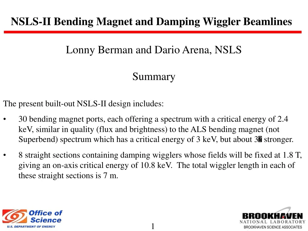
NSLS-II Bending Magnet and Damping Wiggler Beamlines • Lonny Berman and Dario Arena, NSLS • Summary • The present built-out NSLS-II design includes: • 30 bending magnet ports, each offering a spectrum with a critical energy of 2.4 keV, similar in quality (flux and brightness) to the ALS bending magnet (not Superbend) spectrum which has a critical energy of 3 keV, but about 3 stronger. • 8 straight sections containing damping wigglers whose fields will be fixed at 1.8 T, giving an on-axis critical energy of 10.8 keV. The total wiggler length in each of these straight sections is 7 m.
Flux Spectra for NSLS-II Sources and NSLS Bending Magnet Sources
Brightness Spectra for NSLS-II Sources and NSLS Bending Magnet Sources
Distinguishing Source Characteristics and Our Strategy for Their Use • NSLS-II bending magnet sources are very bright from low energies up to hard x-ray energies, and will require only minimal shielding as their spectra are relatively soft • Assign bending magnet sources to address needs from infrared up to about 10 keV, many of which require high brightness (but not exceptionally high brightness which could be satisfied only via access to undulator sources) • Damping wiggler sources will have exceptional power (up to 65 kW) and will be prodigious flux emitters to very high x-ray energies, and will require significant shielding (23 mm lead for side panel of FOE, 50 mm lead for downstream panel of FOE) • Assign damping wiggler sources to address hard x-ray needs (5-50 keV), in particular those that require high flux, large beam sizes, and tunable beams
A Suggested NSLS-II Beamline Distribution (for Bending Magnet and Damping Wiggler Beamlines) *This suggested distribution still leaves available 7 bending magnet ports and 3 damping wiggler ports which could each supply canted wiggler x-ray beams.
Conceptual Layout of VUV / Soft X-Ray Bending Magnet Beamline Elliptical Mirror Plane Mirror Refocusing Mirror Experimental Station Cylindrical Collimating Mirror Exit Slit Plane Grating A Soft X-Ray Microscope Bending Magnet
Conceptual Layout of Hard X-Ray Bending Magnet Beamline Detector Sample Aperture Micro Focusing Mirror (optional) Be Window Double Crystal Mono Focusing Mirror Aperture Aperture Collimating Mirror Be Window Bending Magnet
Canted Damping Wiggler Beamlines • It appears feasible, in the present NSLS-II design, to accommodate canted damping wigglers in individual straight sections (by dividing the 7 m total wiggler length among shorter wigglers), whose radiation emissions are canted by a few milliradians with respect to each other, increasing the number of potential damping wiggler ports. • The larger the canting angle, the larger the impact on the emittance of the ring. E.g. the emittance grows by 12% if two 3.5 m long wigglers canted by 3 mrad with respect to each other are installed in each of these 8 straight sections. Ec = Ec,max(1-[ө/өmax]2)1/2 өmax = K/γ Critical Energy Dependence Across Each Canted Wiggler Radiation Fan 3 mrad 10.8 keV
Conceptual Layout of Two Canted Damping Wiggler Beamlines Detector Lower X-Ray Energy Beamline Sample Be Window Aperture Detector Sample Focusing Mirror Focusing Mirror Double Crystal Mono Be Window Double Crystal Mono Aperture Collimating Mirror Aperture Damping Wiggler Aperture Be Window Higher X-Ray Energy Beamline Damping Wiggler
Layout of Enclosures for Two Canted Damping Wiggler Beamlines FOE for bending magnet beamline FOE for canted damping wiggler beamlines Experimental station for bending magnet beamline Experimental stations for damping wiggler beamlines
A Peek Inside the Enclosures for Canted Damping Wiggler Beamlines
Relatively Few Challenges for Bending Magnet Beamlines • Existing NSLS bending magnet beamline components should be transferrable to NSLS-II bending magnet beamlines without much difficulty, provided they are of proper size, possibly with the exception of focusing mirrors • Existing NSLS bending magnet endstation components should also be transferable to NSLS-II bending magnet endstations • Even monochromatic x-ray beam hutches (if needed) might be transferable, if worth the cost to do so (original construction cost might not differ significantly from dismantling/transportation/reconstruction cost)
A Lot of Challenges for Canted Damping Wiggler Beamlines • Shielding issues for independent canted damping wiggler beamlines, e.g. shutters and scatter shields which act on one beam and not the other: need design and radiological calculation attention, especially in the front ends and FOEs • Component designs for independent canted damping wiggler beamlines: interference issues and heat load issues • If canting isn’t pursued, can a beamline handle the output of a single 7 m long damping wiggler? The power output of 65 kW will be unprecedented for a permanent magnet wiggler (the APS sector 11 wiggler produces 8 kW for K=14, SPring-8 BL08W wiggler produces 14 kW for K=10). The power density is about half that of the 14 mm period superconducting undulator at its highest K. Power reduction measures (filters, pre-mirrors) will have to be considered. Even if the 7 m of available length is divided among shorter canted damping wigglers, these issues are still significant and will merit careful investigation.
Wiggler Absorber SR Wiggler Absorber Glidcop The wiggler absorber clips the radiation fan by about 1 mrad on each side to shadow the downstream exit port. The total intercepted power is 11.6 kW out of 64.6 kW. The absorber is cantilevered from the upstream flange to allow thermal expansion during bakeout.
SR Wiggler Absorber – FE Thermal Analysis About 15 - 20% of the incident power is reflected or scattered. Therefore, the maximum surface temperature is expected to be less than 337ºC.