Download

1 / 13
150 likes | 419 Views
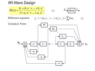
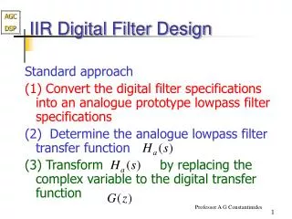
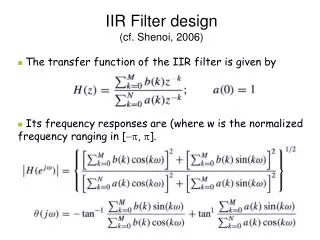
IIR FILTERS DESIGN BY POLE-ZERO PLACEMENT. Prof. Siripong Potisuk. A Narrowband Bandpass Filter. Also known as a resonator Pass a single frequency Place a pole at the point inside the unit circle that corresponds to the resonant freq F 0 The corresponding angle is

E N D
IIR FILTERS DESIGNBY POLE-ZERO PLACEMENT Prof. Siripong Potisuk
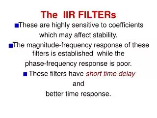
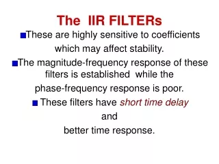
A Narrowband Bandpass Filter • Also known as a resonator • Pass a single frequency • Place a pole at the point inside the unit circle that corresponds to the resonant freq F0 • The corresponding angle is • Place zeros at the two end frequencies, i.e., z = 1 (F = 0) and z = -1 (F = FS/2)
r is chosen such that the filter is highly selective, i.e., small 3-dB BW of the passband, DF. The gain factor b0 is inserted to ensure that the passband gain is1, i.e., no amplification
A Narrowband Bandstop Filter • Also known as a notch filter • Remove a single frequency • Place zeros at the points on the unit circle that correspond to the notch freq F0 • The corresponding angle is • Place poles at the points inside the unit circle that correspond to the notch freq F0
r is chosen such that the filter is highly selective, i.e., small 3-dB BW of the passband, DF. The gain factor b0 is inserted to ensure that the passband gain is1, i.e., no amplification
A Comb Filter • Has several equally spaced passbands • Passes DC, F0, and its harmonics for a total of resonant frequencies, where n is the order of the filter and F0 = FS/n • Place n zeros at the origin • Place n poles at the points equally spaced and inside the unit circle
r is chosen such that the filter is highly selective, i.e., small 3-dB BW of the passband, DF. The gain factor b0 is inserted to ensure that the passband gain is1, i.e., no amplification
An Inverse Comb Filter • A generalization of the notch filter • Eliminates DC, F0, and its harmonics for a total of resonant frequencies, where n is the order of the filter and F0 = FS/n • Place n zeros at the points equally spaced on the unit circle • Place n poles at the points equally spaced and inside the unit circle
r is chosen such that the filter is highly selective, i.e., small 3-dB BW of the passband, DF. The gain factor b0 is inserted to ensure that the passband gain is1, i.e., no amplification
A First-Order Lowpass Filter • A wideband filter • Pass frequency components from 0 to Fc, the cutoff frequency • Place a zero on the unit circle at z = -1 • Place a pole on the real axis and inside the unit circle
The gain factor b0 is inserted to ensure that the passband gain is1, i.e., no amplification
A First-Order Highpass Filter • A wideband filter • Supress frequency components from 0 to Fc, the cutoff frequency • Place a zero on the unit circle at z = 1 • Place a pole on the real axis and inside the unit circle
The gain factor b0 is inserted to ensure that the passband gain is1, i.e., no amplification