Download
1 / 13
130 likes | 274 Views
Leg Assembly. A step-by step guide to the disassembly and service of a HUBO leg. The Left Leg. Hip (3 axes). Knee.

E N D
Leg Assembly A step-by step guide to the disassembly and service of a HUBO leg
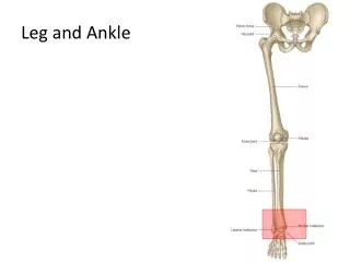
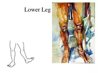
The Left Leg Hip (3 axes) Knee The left leg shown above has 6 total DOF. The 3 axes of the hip are not shown (will insert later). A single axis is used for the knee, while the ankle joint allows the foot to articulate in 2 axes. The 6 leg axes are the minimum required to accurately mimic human gait. Ankle (2 axes)
Hip Joint The hip joint combines 3 independent joint axes as shown to the left. To simplify inverse kinematics, a series combination of axes was used. The most complicated assembly on the entire robot is the 2-axis joint for the hip, at the bottom left. (Note: The hip joint is currently being serviced in the shop, so I’ll be able to write a full discourse as soon as it’s delivered) Internal drive on one of the axes
Upper Leg After removing the hip joint and electronics boards, the knee’s drive is clearly visible. The outer knee joint bearing is a part of the pulley cover, as shown to the left. The use of 2 motors doubles the power to the knee joint. This requires careful balancing of the current to each motor so that they both operate at maximum efficiency. (further explanation to come in the electrical tutorial)
After removing the pulleys, the motor mount bolts are visible. The oval mounting holes in the leg allow small adjustments of the motor to tighten the belt. Newer designs use an external belt tensioner,
Remove the Upper Leg • Remove the curved plate at the bas of the hip (8 bolts total) • Remove 3 bolts from each side of the knee to separate the upper and lower leg. This allows the easy access to the knee joint.
Disassemble the knee joint The knee joint and upper leg is now fully disassembled. Reassembly simply reverses the steps. At this point, the gear and bearings of the harmonic drive are fully accessible for service. A tap from a soft hammer on the shaft (opposite side) removes these parts. The harmonic drive (shown below) uses the factory standard flanges, and so is typically purchased as a unit. (Will include complete disassembly/reassembly in next version)
The plates of the lower leg are easily removed without the knee structure. Unbolt the 2 round cross braces and gently slip the bearing off of the mount at the ankle joint. To remove the left side plate, unbolt the bearing and cover of the transverse axis as shown:
Ankle Joint • Loosen the harmonic drive by removing 6 bolts (alternating sides in a star pattern) • Loosen the pulley on the driveshaft with a long hex key. This requires a ball-end key to clear the motor. • Unbolt the motor mount (remove 3 bolts) • Tilt and remove the motor and belt to free the driveshaft.
Ankle Joint Mount plate for 2nd axis harmonic drive Bearing unit set screws To remove the harmonic drive, pull gently on the body. The pulley can slide about a centimeter internally before hitting an obstruction (the mount plate shown above). This gap is enough to reach to set screws on the rotor of the harmonic drive. Simply loosen them and slide the drive gently off of the shaft. With some effort, the shaft can be pulled from the pulley as well.
Ankle Joint Housing • Unbolt harmonic drive mount • Carefully loosen each of 6 bolts holding the bearing mount in place. Unbolt in a star pattern to avoid damaging the plate or breaking a bolt head. • Separate the 3 pieces. Parts can now be cleaned, modified, and realigned.
Foot Loosen in increments of ¼ turn or less as shown: 1 1 4 3 2 • The ankle bracket can be unbolted from the Force/Torque sensor by carefully loosening the 4 bolts. Since all of the load on the leg is borne through this small joint, it is critical that the bolts be tightened evenly. Uneven tightening could warp the sensor and affect the strain gage readings. • Unbolt the F/T sensor from the foot plate in the same manner. • The components of the foot can now be serviced or replaced. 2 3