Download
1 / 18
180 likes | 338 Views
WORKSHOP 1 LANDING GEAR STRUT ANALYSIS. NAS120, Workshop 1, November 2003. WS1- 1. Problem Description A landing gear strut has been designed for a new fighter jet. Determine if the landing gear strut has been designed properly to withstand the landing load. E = 30 x 10 6 psi

E N D
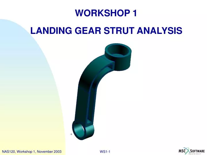
WORKSHOP 1 LANDING GEAR STRUT ANALYSIS NAS120, Workshop 1, November 2003 WS1-1
Problem Description • A landing gear strut has been designed for a new fighter jet. Determine if the landing gear strut has been designed properly to withstand the landing load. • E = 30 x 106 psi • n =0.3 • Landing Load = 7,080 lb
Workshop Objectives • Learn the typical workflow of a finite element analysis using MSC.Patran and MSC.Nastran.
Suggested Exercise Steps • Create a new database and name it strut.db. • Import the strut geometry. • Mesh the strut to create solid elements. • Apply Loads and Boundary Conditions. • Create material properties. • Create physical properties. • Run analysis with MSC.Nastran. • Read the results into MSC.Patran. • Plot the Von Mises stress and displacement.
Step 1. Create New Database a a • Create a new database called strut.db • File / New. • Enter strut as the file name. • Click OK. • Choose Tolerance Based on Model. • Select MSC.Nastran as the Analysis Code. • Select Structural as the Analysis Type. • Click OK. d e f b c g
Step 2. Import Geometry a • Import the parasolid file • File : Import. • Select the file strut.xmt. • Click Apply. b c
Step 3. Mesh the Object f Create a solid mesh • Elements: Create / Mesh / Solid. • Select the entire solid. • Deselect Automatic Calculation under Global Edge Length. • Enter 0.5 for the Global Edge Length. • Click Apply. • Click on the Iso2 View Icon. a b c d e
Step 4. Apply Loads and Boundary Conditions Create a boundary condition • Loads/BCs: Create / Displacement / Nodal. • Enter hub cylinder as the New Set Name. • Click Input Data. • Enter <0 0 0> for Translations. • Click OK. a d b c e
Step 4. Apply Loads and Boundary Conditions Apply the boundary condition • Click Select Application Region. • For the Geometry Filter select Geometry. • Set the Selection Filter to Surface or Face and select the cylinder at the bottom of the strut, as shown. • Click Add. • Click OK. • Click Apply. b c d a e f
Step 4. Apply Loads and Boundary Conditions Create a load • Loads/BCs: Create / Total Load / Element Uniform. • Enter landing load as the New Set Name. • Click Input Data. • Enter <0 –7080 0> for Load. • Click OK. a d b c e
Step 4. Apply Loads and Boundary Conditions Apply the load • Click Select Application Region. • For the Geometry Filter select Geometry. • Select the upper circular surface at the top of the strut, as shown. • Click Add. • Click OK. • Click Apply. b c d a e f
Step 5. Create Material Properties Create an isotropic material • Materials: Create / Isotropic / Manual Input. • Enter steel for the Material Name. • Click Input Properties. • Enter 30e6 for the Elastic Modulus. • Enter 0.3 for the Poisson Ratio. • Click OK. • Click Apply. a d e b c f g
Step 6. Create Physical Properties Create physical properties • Properties: Create / 3D / Solid. • Enter strut as the Property Set Name. • Click Input Properties. • Select steel as the material. • Click OK. a d b c e
Step 6. Create Physical Properties Apply the physical properties • Click in the Select Members box. • Screen pick the entire solid as shown. • Click Add. • Click Apply. b a c d
Step 7. Run Linear Static Analysis Analyze the model • Analysis: Analyze / Entire Model / Full Run. • Click Solution Type. • Choose Linear Static as the Solution Type. • Click OK. • Click Apply. a c b d e
Step 8. Read Results into MSC.Patran Attach the results file • Analysis: Access Results / Attach XDB / Result Entities. • Click Select Results File. • Choose the results file strut.xdb. • Click OK. • Click Apply. a c d b e
Step 9. Plot Stress and Displacement e Create a quick plot • Results: Create / Quick Plot. • Select Stress Tensor as the Fringe Result. • Select Displacements, Translational as the Deformation Result. • Click Apply. • Click on the Iso1 View Icon. a b c d