Download
1 / 23
230 likes | 342 Views
Overview of CLIC system tests R. Corsini for CLIC Collaboration. OUTLINE: Why & how do we need system tests? CLIC peculiarities - CTF3 as a system test Other ongoing system tests Future plans/needs. Why do we need system tests?.

E N D
Overview of CLIC system testsR. Corsini for CLIC Collaboration OUTLINE: Why & how do we need system tests? CLIC peculiarities - CTF3 as a system test Other ongoing system tests Future plans/needs
Why do we need system tests? Linear colliders rely on complex technical systems, composed of many individual components. Often, only an integrated test is able to assess the soundness of a system as a whole. The need for (and the goals of) system tests naturally evolve during the evolution of the study: • Ensure feasibility, initial risk reduction • Quantify and/or predict performance • Assess cost • Re-optimize design for cost, performance and risk. Converge on technical design. • Prepare industrialization
System tests issues • Definition & scope: it’s not always clear what a “system” is. The linear collider may indeed be thought as a huge, single system – where to stop? What is a meaningful sub-system to be tested? How to define boundaries? What about cross-talk between systems? • Problem of scale/completeness: a system test is most of the time a scaled/simplified version of the final system. What is a reasonable scaling down? Should all details be included? How to define goals? How to scale up the experimental results? Other issues: What to measure? Beam tests are always needed? How representative a “probe beam” should be? …
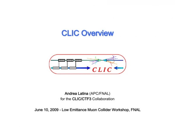
CLIC Layout at 3 TeV The ultimate CLIC system test Drive beam time structure - initial Drive beam time structure - final Drive Beam Generation Complex 240 ns 240 ns 5.8 ms 140 ms train length - 24 24 sub-pulses 4.2 A- 2.4 GeV – 60 cm between bunches 24 pulses – 101 A– 2.5 cm between bunches Main Beam Generation Complex
CLIC Test Facility (CTF3) Operation of isochronous lines and rings 4 A, 1.4us 120 MeV 30 A, 140 ns 120 MeV High current, full beam-loading operation Beam recombination and current multiplication by RF deflectors 12 GHz power generation by drive beam deceleration High-gradient two-beam acceleration 30 A, 140 ns 60 MeV Bunch phase coding
What do we learn in CTF3, relevant for the CLIC RF power source ? A non-exhaustive list easier more difficult System quantity/issue CTF3 CLIC Injector/linac bunch charge 2-3 nC6.7 nC current 3.5 - 4.5 A 4.2 A pulse length 1.4 ms140 ms phase coding same frequency 3 GHz1 GHz transverse stability about the same - CTF3 ``too stable ´´ Delay loop/ring final current28A100 A beam energy 125 MeV2.4 GeV combination2 - 42 - 3, 4 CSR, wakes worse in CTF3 (lower energy) Deflector instability about the same Power production (PETS) Aperture 23 mm 23 mm Length 1 m23 cm Power > 135 MW 135 MW Pulse length 140 ns (260 ns with recirculation) 240 ns Decelerator Fractional loss 50 %90% Final energy60 MeV240 MeV wakes, stability somehow ``masked´´ in CTF3 beam envelope much larger in CTF3 In general, most of detrimental effects are equivalent or worse in CTF3 because of the low energy, however in CLIC the beam power is much larger (heating, activation, machine protection) Needed tolerances on the final drive beam parameters (phase, current, energy stability...) are more stringent in CLIC – some could beare being demonstrated in CTF3 as well
Beam Delivery System (ATF 2) • Philippe Bambade, CLIC Collaboration Workshop, May 2012 Shintake Monitor
Beam Delivery System (ATF 2) Probability to achieve more than L/L0 [%] Goal Simulated full tuning performance
Damping Ring • Yannis Papaphilippou, CLIC Collaboration Workshop, May 2012 • DR beam dynamics studies • Low Emittance Tuning (SLS, Australian Synchrotron) • IBS (CESRTA, SLS) • E-cloud (CESRTA) • CSR (ANKA, ATF) • Optics, non-linear correction (DIAMOND, SOLEIL) • Fast Ion Instability (SOLEIL) • Instabilities (SLS) M. Aiba, M. Boge, N. Milas, A. Streun • DR technical systems R&D • Super-conducting wigglers (BINP, tested in ANKA) • High frequency RF system (ALBA and SLAC) • Coatings, chamber design and ultra-low vacuum (SPS, ESRF, CERTA, MAXlab) • Kicker technology(Spanish industry, ALBA, SLAC, test in ATF) • Diagnostics for low emittance(V-UV Profile Monitor - TIARA) Inductive Adder SC wiggler
Damping Ring • Yannis Papaphilippou, CLIC Collaboration Workshop, May 2012
Two-Beam Modules Ongoing: Fabrication of 4 modules to be mechanically tested in laboratory Next Step: Installation and test of full-fledged Two-Beam Modules in CLEX First module in development, installation end 2013 Three modules in 2014-2016
Two-Beam Modules 3D model of integration of the first CLIC Module in CLEX (2013) Module T0 TBTS PETS tank CLEX - Three two-beam modules (2014) Main Beam line Drive Beam line Present schedule: First module installation end 2013 (At least one year of testing) Module string installation end 2014
Emittance Preservation – Main linac Beam-Based Alignment • Andrea Latina, CLIC Collaboration Workshop, May 2012
Emittance Preservation – Main linac Beam-Based Alignment T501: FACET test-beam proposal to study advanced global correction schemes for future linear colliders. CERN-SLAC collaboration where algorithms developed at CERN are tested on the SLAC linac. The study includes linac system identification, global orbit correction and global dispersion correction. Successful system identification and global orbit correction has been demonstrated on a test-section of 500 m of the linac. The section of the SLAC beamlines we work on RESULT: Example of global orbit correction of a test-section of the SLC linac: (above) Horizontal and Vertical trajectories before and after orbit correction (Above) Measured Rx response matrix for the test-section of the linac (17 correctors, 48 BPMs) (above) Iterations of orbit correction: convergence of the algorithm
Some CLIC Drive Beam requirements Tests in CTF3 Tests in CTF3 Emittanceεx,y≤ 150μm Transverse jitter ≤ 0.3σ Current stability 0.75 10-3 Phase stability 0.2° @ 12GHz Bunch length stability 1% Feed-forward tests in CTF3 RF power stability 0.2% RF phase stability 0.05° Current stability 0.1% Phase stability 2.5° @ 12GHz 0.2° @ 1GHz Verified in CTF3 Tests in CTF3
Drive Beam phase feed-forward tests Phase stability 0.2° @ 12GHz Fast kickers CLIC drive beam phase feed-forward concept Phase monitor Phase stability 2.5° @ 12GHz 0.2° @ 1GHz CTF3 - Phase feed-forward FONT5 board (Oxford) • Not just a single experiment – series of related studies: • Measure phase and energy jitter, identify sources, devise & implement cures, extrapolate to CLIC • Show principle of CLIC fast feed-forward Stripline kicker (INFN-LNF) • Close link to collaborating partners: • INFN-LNF: Phase monitors, stripline kickers • Oxford University/JAI: feedback electronics, amplifiers
Drive Beam phase feed-forward tests Phase stability 0.2° @ 12GHz Fast kickers CLIC drive beam phase feed-forward concept Phase monitor Phase stability 2.5° @ 12GHz 0.2° @ 1GHz CTF3 - Phase feed-forward • Not just a single experiment – series of related studies: • Measure phase and energy jitter, identify sources, devise & implement cures, extrapolate to CLIC • Show principle of CLIC fast feed-forward Phase monitor (INF-LNF, EuCARD) • Close link to collaborating partners: • INFN-LNF: Phase monitors, stripline kickers • Oxford University/JAI: feedback electronics, amplifiers Phase monitor prototypes installed.Test starting in 1-2 weeks
Drive Beam Front-End Modulator-klystrons, 1 GHz, 15 MW IOTs, 500 MHz CTF3 Injector Diagnostics Sub-Harmonic Buncher RF design 10-20 MeV SHB 1-2-3 Gun PB Buncher Acc. Structures
Drive Beam Front-End issues • Develop and demonstrate Drive Beam Accelerator RF unit at full pulse length: High efficiency klystron @ 1 GHz High efficiency and stable modulator Fully loaded, HOM damped 1 GHz accelerating structure (validate technology) • Electron source technology R&D: Cathode and HV pulser. Life time, reliability, routine operation. • Performance of drive beam front-end: beam quality and stability with long pulse: Current stability ~ 0.1% Beam phase stabilityEmittance and energy and position jitter Phase coding at 1 GHz • Develop diagnostics suitable for long pulse and machine protection. • DB front-end will be suitable for CLIC zero and CLIC
Dream test facility – emittance generation/preservation/beam delivery • Daniel Schulte, CLIC Collaboration Workshop, May 2012 Injector Note: FFTB has been similar But with εy= O(1μm) Reached σy=70nm (design 50nm) Low emittance ring, e.g. 3rd generation light source, damping ring test facility Main linac with bunch compressor Powered with drive beam or X-band klystrons BDS test facility Example options: SPS as damping ring (combined with CLIC0?), FACET with improved damping ring? ATF, PEP-II, ESRF, SLS, SPRING-8, … Bypassing the damping ring, one can use the linac as a 4th generation light source Maybe some benefit in using ring and linac together as light source or for other experiments, e.g. ATF3
Example Parameters • Daniel Schulte, CLIC Collaboration Workshop, May 2012 • 3TeV structure, 108 quadrupoles, 324 super-structures, 2GeV initial energy, 250μm bunch length, 0.8*3.7e9 particles • Amplification of jitter emittance -> 4.7 • 3.5um cavity scatter -> 0.14nm • 14um BPM scatter -> 14nm • Could use other structures and adjust bunch charge • A power unit consists of • A pair of 50MW X-band klystrons with pulse length 1.6us • A pulse compressor with compression factor 6 -> 244ns + • Power gain is about 4.2 • Splitter into three superstructures (6 structures) • i.e. 70MW/structure • Significant cost could be reduced by • Not power all structures • Using different structures • Contribution from user community
CLIC Zero Probe-beam injector 0.25 GeV, 1.2 A TBA 6.5 GeV, 1.2 A 0.2 GeV, 101 A DB Turn around0.48 GeV, 101 A CR1 DBA 0.48 GeV, 4.2 A CR2 DL 100 m