Download
1 / 3
30 likes | 37 Views
Before opening the panel or door on a motor controller, prescan the enclosure to assure a safe opening condition. If excessive heat appears on the surface of the door, extra care should be taken when opening it

E N D
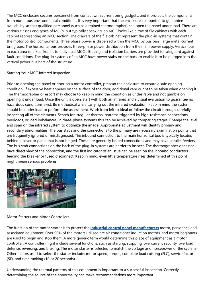
The MCC enclosure secures personnel from contact with current bring gadgets, and it protects the components from numerous environmental conditions. It is very important that the enclosure is mounted to guarantee availability so that qualified personnel (such as a trained thermographer) can open the panel under load. There are various classes and types of MCCs, but typically speaking, an MCC looks like a row of file cabinets with each cabinet representing an MCC section. The drawers of the file cabinet represent the plug-in systems that contain the motor control components. Three phase power is dispersed within the MCC by bus bars, large metal current bring bars. The horizontal bus provides three-phase power distribution from the main power supply. Vertical bus in each area is linked from it to individual MCCs. Bracing and isolation barriers are provided to safeguard against fault conditions. The plug-in systems of an MCC have power stabs on the back to enable it to be plugged into the vertical power bus bars of the structure. Starting Your MCC Infrared Inspection Prior to opening the panel or door on a motor controller, prescan the enclosure to ensure a safe opening condition. If excessive heat appears on the surface of the door, additional care ought to be taken when opening it. The thermographer or escort may choose to keep in mind the condition as undesirable and not gamble on opening it under load. Once the unit is open, start with both an infrared and a visual evaluation to guarantee no hazardous conditions exist. Be methodical while carrying out the infrared evaluation. Keep in mind the system should be under load to perform the assessment. Work from left to ideal or follow the circuit through carefully, inspecting all of the elements. Search for irregular thermal patterns triggered by high-resistance connections, overloads, or load imbalances. In three-phase systems this can be achieved by comparing stages. Change the level and span on the infrared system to optimize the image. Appropriate adjustment will identify primary and secondary abnormalities. The bus stabs and the connections to the primary are necessary examination points that are frequently ignored or misdiagnosed. The inbound connection to the main horizontal bus is typically located behind a cover or panel that is not hinged. These are generally bolted connections and may have parallel feeders. The bus stab connections on the back of the plug-in systems are harder to inspect. The thermographer does not have direct view of the connection, and the first indicator of an issue can be seen on the inbound conductors feeding the breaker or fused disconnect. Keep in mind, even little temperature rises determined at this point might mean serious problems. Motor Starters and Motor Controllers The function of the motor starter is to protect the industrial control panel manufacturers motor, personnel, and associated equipment. Over 90% of the motors utilized are air conditioner induction motors, and motor beginners are used to begin and stop them. A more generic term would determine this piece of equipment as a motor controller. A controller might include several functions, such as starting, stopping, overcurrent security, overload defense, reversing, and braking. The motor starter is selected to match the voltage and horsepower of the system. Other factors used to select the starter include: motor speed, torque, complete load existing (FLC), service factor (SF), and time ranking (10 or 20 seconds). Understanding the thermal patterns of this equipment is important to a successful inspection. Correctly determining the source of the abnormality can make recommendations more important.
Overcurrents up to locked rotor current are typically triggered by mechanical overloading of the motor. The four typical varieties of motor starters are: across-the-line, the reversing starter, the multispeed starter, and the reduced voltage starter. Motor beginners are typically comprised of the very same types of elements. Overcurrent Protection NEC needs overcurrent protection and a way to disconnect the motor and controller from line voltage. Fused disconnects or thermal magnetic breaker are typically used for overcurrent protection and to provide a detach for the circuit. A circuit breaker is specified in NEMA standards as a gadget designed to open and close a circuit by non-automatic methods and to open the circuit immediately on a predetermined overcurrent without injury to itself when effectively applied within its ranking. If we look at a cutaway of a breaker, we can identify prospective connection issues. The line side and load side lugs are the most common source of abnormal heating, but numerous breakers have a second set of bolted connections on the back of the breaker. Heat from this connection can be misdiagnosed as the main lug. There are likewise internal contacts where existing flow is disrupted by working out the element. These contacts experience arcing each time the breaker is opened. An arc is a discharge of electrical current jumping across an air space between 2 contacts. Arcs are formed when the contacts of a breaker are opened under a load. Arcing under typical loading is extremely small compared to an arc formed from a brief circuit disturbance. Arcing produces additional heat and can harm the contact surface areas. Harmed contacts can trigger resistive heating. Thermal patterns from these bad connections appear as diffuse heating on the surface area of the breaker. In addition, there are numerous types of breakers that have actually internal coils used for circuit defense. These coils have actually heat related to them and can seem an internal heating issue, when in reality, it is a regular condition. Fused Disconnects Fused disconnects are utilized to supply over-current security for motor in the very same manner as a breaker. Instead of opening contacts, merges fail opening the circuit. When overcurrent security is supplied by merges, a detach switch is required for manual opening of the circuit. The detach switch and fuse block are usually one assembly. The hinge and blade connections on the switch are a normal source of getting too hot. High resistance from overuse or underuse is normally the cause. Fuse clips are likewise a weak connection point for some disconnect designs. Various types or producers of merges of the very same amperage might produce various thermal signatures. While various size or amperage merges will also have a different thermal pattern, fuse bodies may appear warmer than the rest of the circuit due to conductor size. Contactors Beginners are made from 2 building blocks, contactors and overload defense. Contactors control the electric existing flow to the motor. Their function is to repeatedly develop and disrupt an electrical power circuit. A contactor can base on its own as a power control device, or as part of a starter. Contactors run electromechanically and use a small control present to open and close the circuit. The electromechanical elements do the work, not the human hand, as holds true with a knife blade switch or a manual controller. The series of operation of a contactor is as follows: initially, a control present is used to the coil; next, current circulation into the coil produces a magnetic field which magnetizes the E-frame making it an electromagnet; lastly, the electromagnet draws the armature towards it, closing the contacts. A contactor has a life expectancy. If the contactor contacts are
frequently opened and closed, it will reduce the life of the unit. As the contacts are worked out, an electrical arc is created between the contacts. Arcs produce heat, which can damage the contacts. Contacts eventually end up being oxidized with a black deposit. This black deposit may really improve the electrical connection in between the contacts by improving the seat, but burn marks, pitting, and corrosion show it is time to replace the contacts. The following thermal patterns are related to contactors. The coil of the contactor is normally the hottest part of the unit. High temperatures might suggest a breakdown of the coil. Line side and load side lug connections may show high resistance heating from bad connections. Heating from burned and pitted contacts might be thermally "noticeable" on the body of the contactor. Overload Protection The perfect motor overload defense is a system with current noticing abilities comparable to the heating curve of the motor. It would open the motor circuit when full load current is surpassed. Operation of this gadget would enable the motor to run with safe temporary overloads, but open up when an overload lasts too long. Typical thermal issues in overloads are found in the connections to the contactor, overload relay, or motor. The overload relay restricts the amount of current drawn to safeguard the motor from overheating. The relay measures the temperature level of the motor by keeping an eye on the amount of existing being drawn. Normal thermal problems in overloads are discovered in the connections to the contactor, overload relay, or motor. Beginners Starters are the combination of a controller, usually a contactor and an overload relay. The above descriptions of the private elements use to the starter systems. Lowered voltage starters are utilized in applications that include large horsepower motors. They are used to decrease the in-rush existing and restrict the torque, and thus the mechanical tension on the load. The parts of this kind of starter ought to be inspected as the motor steps up to speed. A separate low-voltage starter circuit is utilized to step the motor up to speed. When at running speed, these elements are de-energized. Completing Inspections Various fuse types and sizes will cause various thermal signatures as will overload relays that are sized in a different way within the very same circuit. Step loads where component sizing, overwhelming, or load imbalances are observed. Be careful of the results of wind or convection on elements. Conclusion Understanding the equipment under inspection enables for the correct recognition of problems that might be misdiagnosed or neglected. Examining unknown thermal patterns on a part is easier when equipment style is reviewed.